


36 ASUS A7A266-E User’s Manual
3. HARDWARE SETUP
Connectors
3. H/W SETUP
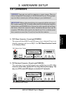
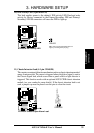
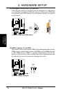
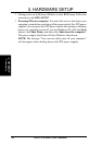
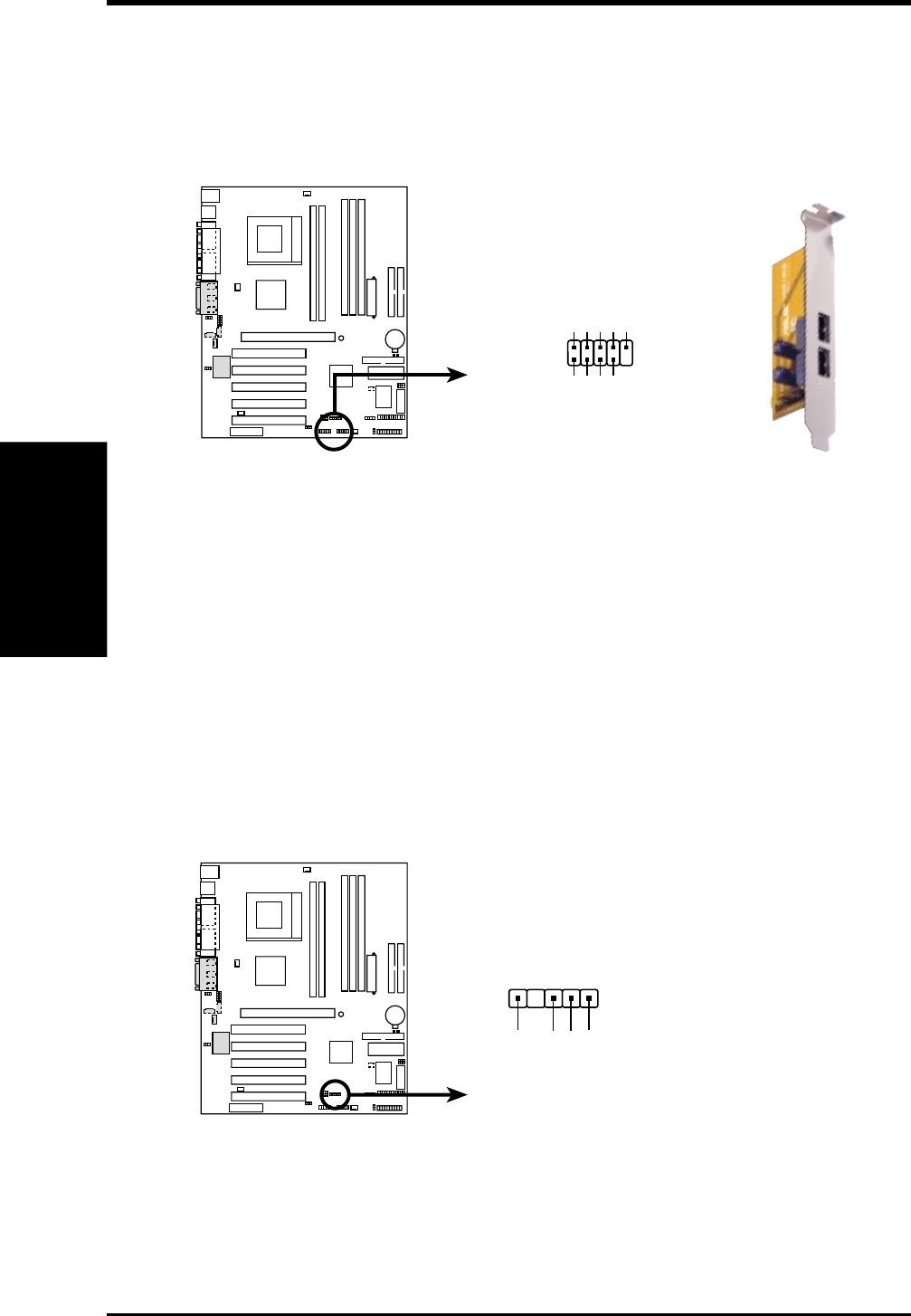
15) USB Headers (10-1 pin USB1, 10-1 pin USB2)
If the USB port connectors on the back panel are inadequate, two USB headers
are available for four additional USB port connectors. Connect each USB header
to an optional 2-port USB connector set and mount the bracket to an open slot
on your chassis.
0101
A7A266-E
A7A266-E Front Panel USB Headers
USB1
USB2
USB Power
USBP2–
USBP2+
GND
NC
USB Power
USBP3–
USBP3+
GND
15
610
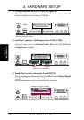
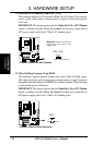
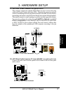
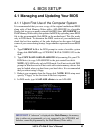
16) SMBus Connector (5-1 pin SMB)
This connector allows you to connect SMBus (System Management Bus) devices.
SMBus devices communicate by means of the SMBus with an SMBus host and/
or other SMBus devices. SMBus is a specific implementation of an I
2
C bus,
which is a multi-device bus; that is, multiple chips can be connected to the same
bus and each one can act as a master by initiating data transfer.
0101
A7A266-E
A7A266-E SMBus Connector
SMBCLK
Ground
SMBDATA
+5V
1
SMB