


ASUS A7A266-E User’s Manual 37
3. HARDWARE SETUP
Connectors
3. H/W SETUP
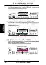
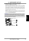
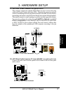
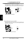
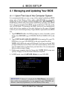
17) ASUS IrDA / iPanel Connector (24-1 pin AFPANEL)
This connector supports an optional ASUS iPanel, an easy to access drive bay
with front I/O ports, buttons and status LEDs. Alternatively, connect an optional
wireless transmitting and receiving infrared module to the SIR for both wireless
transmitting and remote control functions through one external infrared module.
This module mounts to a small opening on system cases that support this feature.
You must also configure the setting through UART2 Use Infrared (see 4.4.2 I/
O Device Configuration) to select whether UART2 is directed for use with COM2
or IrDA. Use the five pins as shown in Back View and connect a ribbon cable
from the module to the motherboard’s SIR connector according to the pin
definitions.
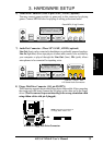
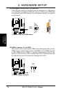
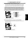
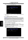
18) ASUS iPanel Audio Connector (12-1 pin AAPANEL) (on audio model only)
Connect the audio cable from the optional ASUS iPanel to this for front panel
audio control.
0101
A7A266-E
A7A266-E Front Panel Connectors
Standard Infrared (SIR)
Front View Back View
+5V
IRTX
IRRX
(NC)
GND
+5VSB
NC
+5 V
GND
CIRRX
NC
GND
IRRX
IRTX
CIR
SIR
IR_CON
+5VSB
NC
CHASSIS#
+5 V
PCIRST#
GND
CIRRX
EXTSMI#
MLED-
NC
BATT
NC
SMBDATA
GND
+3VSB
IRRX
IRTX
LOCKKEY
NC
NC
+5V SMBCLK
AFPANEL
0101
A7A266-E
A7A266-E Audio Panel Connector
MICPWR
Line in_R
Line in_L
MIC2
Line out_L
AGND
AGND2 AGND3
Line out_R
AAPANEL