


32 ASUS P2B-N User’s Manual
3. HARDWARE SETUP
Connectors
3. H/W SETUP
3.8 External Connectors
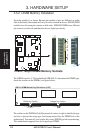
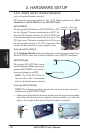
IMPORTANT: Ribbon cables should always be connected with the red stripe to
Pin 1 on the connectors. Pin 1 is usually on the side closest to the power connec-
tor on hard drives and CD-ROM drives, but may be on the opposite side on
floppy disk drives. Check the connectors before installation because there may
be exceptions. IDE ribbon cables must be less than 46 cm (18 in.), with the
second drive connector no more than 15 cm (6 in.) from the first connector.
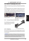
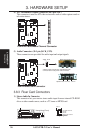
3.8.1 Back Panel Connectors
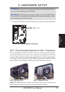
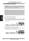
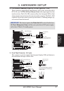
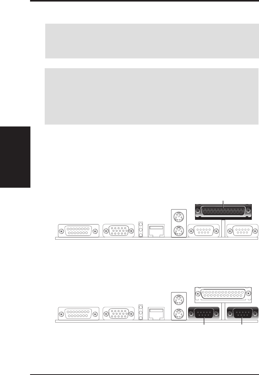
1) Parallel Connector (25-pin PRINTER)
You can enable the parallel port and choose the IRQ through Onboard Parallel
Port in 4.5 Chipset Features Setup. NOTE: Serial printers must be connected
to the serial port.
Parallel Port (25-pin female)
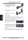
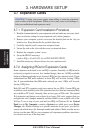
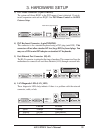
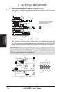
2) Serial Port Connectors (9-pin COM1 and COM2)
The two serial ports can be used for pointing devices or other serial devices. See
Onboard Serial Port in 4.5 Chipset Features Setup.
COM 2 COM 1
Serial Ports (9-pin male)
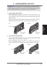
WARNING! Some pins are used for connectors or power sources. These are
clearly separated from jumpers in 3.1 Motherboard Layout. Placing jumper
caps over these will cause damage to your motherboard.