


ASUS P2B-N User’s Manual 37
3. HARDWARE SETUP
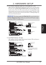
Connectors
3. H/W SETUP
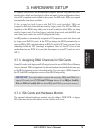
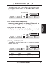
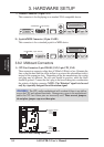
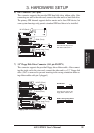
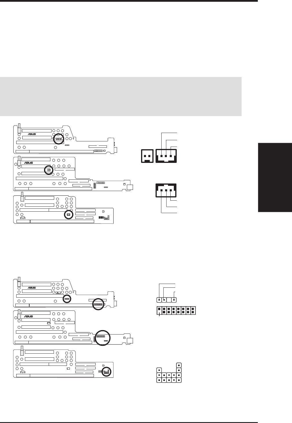
2) LAN Activity Connectors (2-pin LAN_LED & 3-pin WOL_CON)
These connectors support Local Area Network (LAN) cards, such as the ASUS
PCI-L101 (see 7.1 PCI-L101 Fast Ethernet Card) with output signals for data
transfer activity. The LAN_LED connector allows the front panel LED to flash
during transfer activity between the network and the computer. The WOL_CON
connector allows the system to power up when there is a wakeup package (sig-
nal) received from the network.
IMPORTANT: This feature requires that Wake On LAN is set to Enabled (see
4.6 Power Management Setup) and that your system has an NLX power supply
with at least 720mA +5V standby power.
LAN Activity Connectors
+5 Volt Standby
PME
Ground
®
NLX-R
®
B9-N
YEONG-YANG
NLX-R (Front)
B9-N (Front)
Yeong-Yang (Front)
+5 Volt Standby
PME
Ground
B9-N Riser
NLX-R & Yeong-Yang Risers
+
WOL_CON
LAN_LED
(NLX-R only)
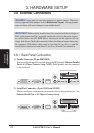
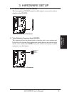
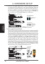
3) Front Panel Connector (16-1 pins)
This connector is used to connect the front panel display LEDs and buttons to
the motherboard through a ribbon cable.
Front Panel Display and Button Connector
YEONG-YANG
Yeong-Yang (Front)
B9-N (Front)
®
B9-N
®
NLX-R
NLX-R (Front)
1
1
Speaker Connector
Power LED
HDD LED
Reset Switch
Power Switch
+
-
+
-
+
+
+
-
-
-
Pin 1
The front panel display & buttons
connect to the riser card through
a ribbon cable.
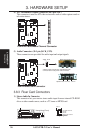
LED_CTRL
FCON
Right Audio Channel
Ground
1
4
Left Audio Channel