


38 ASUS P2B-N User’s Manual
3. HARDWARE SETUP
Connectors
3. H/W SETUP
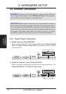
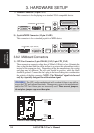
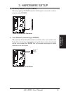
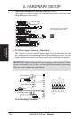
4) Front Panel Microphone Connector (2-pin MIC-CON)
This connector is used to connect the front panel microphone jack to the moth-
erboard through a ribbon cable.
Front Panel Microphone Jack
The front panel’s 1/8” microphone
jack connects to the riser card
through a ribbon cable
®
NLX-R
®
B9-N
YEONG-YANG
NLX-R (Front)
B9-N (Front)
Yeong-Yang (Front)
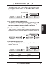
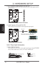
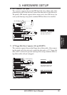
5) NLX Power Supply Connector (20-pin block)
This connector connects to an NLX power supply. The plug from the power sup-
ply will only insert in one orientation because of the different size holes. Find the
proper orientation and push down firmly making sure that the pins are aligned.
IMPORTANT: Make sure that the NLX power supply can deliver at least 720mA
on the 5volt standby lead (+5VSB). You may experience difficulty in powering
ON your system without this specification.
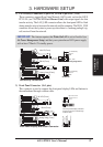
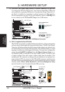
NLX Power Connector
+3.3 Volts
-12.0 Volts
Ground
Power Supply On
Ground
Ground
Ground
-5.0 Volts
+5.0 Volts
+5.0 Volts
Power Good
+12.0 Volts
+3.3 Volts
+3.3 Volts
Ground
+5.0 Volts
Ground
+5.0 Volts
Ground
+5V Standby
NLX-R (Back)
B9-N (Back)
Yeong-Yang (Back)
NLX Power Supply Connector