


40 ASUS P2B-N User’s Manual
3. HARDWARE SETUP
Connectors
3. H/W SETUP
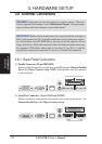
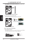
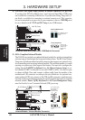
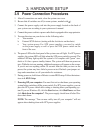
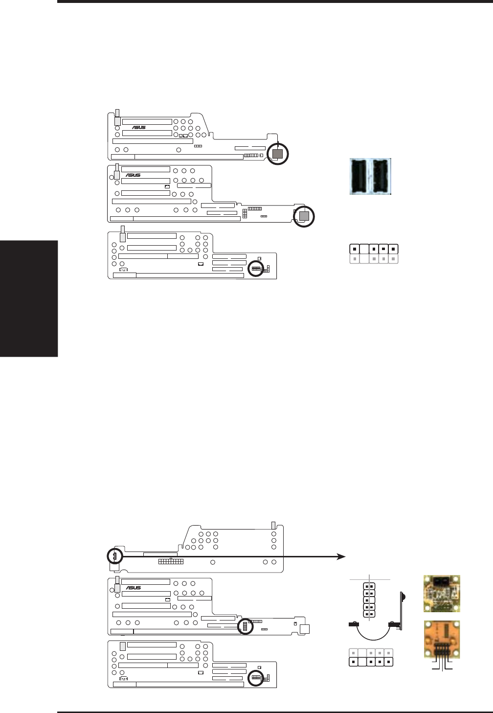
8) USB Ports (Two 4-pin Female Sockets) & Module Connector (5-1 pin USB)
If you have the NLX-R or B9-N risers, two Universal Serial Bus (USB) ports
are available for connecting USB devices. If you have the Yeong-Yang riser, a 5-
pin block is available for connecting an external connector set. This connector
set can be mounted to an open slot on your computer’s chassis. USB IRQ must
be set to Enabled in 4.7 PNP and PCI Setup to use USB features.
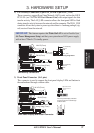
Universal Serial Bus (USB) Ports / USB Module Connector
Yeong-Yang (Front)
YEONG-YANG
1: USB +5 Volt
2: (no connection)
3: USB Port 0+
4: USB Port 0-
5: GND
The USB ports show
through the front
panel
Port 1 Port 2
B9-N (Front)
®
B9-N
NLX-R & B9-N Risers
15
Yeong-Yang Riser
®
NLX-R
NLX-R (Front)
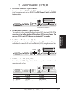
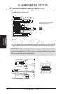
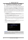
9) IrDA-Compliant Infrared Module
The NLX-R riser includes an onboard infrared module for wireless transmitting
and receiving of data through the front panel infrared lense. The B9-N and Yeong-
Yang risers include an infrared module connector that supports an optional wire-
less transmitting and receiving infrared module. This module mounts to a small
opening on system cases that support this feature. You must also configure the
setting through UART2 Use Infrared (see 4.5 Chipset Features Setup) to se-
lect whether UART2 is directed for use with COM2 or IrDA. Use the five pins
as shown in Back View and connect a ribbon cable from the module to the
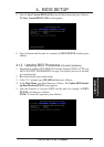
motherboard’s IR connector according to the pin definitions. An optional con-
sumer infrared (CIR) set connects to the CIR and IR connectors simultaneously
for both wireless transmitting and remote control functions through one external
infrared module. Power Up By Keyboard in 4.6 Power Management Setup
must be Enabled to use Consumer Infrared (CIR) power up.
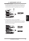
Infrared Module / Infrared Module Connector
Yeong-Yang (Front)
YEONG-YANG
The module sends
data through the
front panel’s
infrared window
NLX-R (Back)
®
B9-N
B9-N (Front)
1
5
1: +5 Volt
2: (no connection)
3: IRRX
4: GND
5: IRTX
Back View
+5V
IRTX
IRRX
FIR/(NC)
GND
Front View
IR
12
10
9
IRTX
+5V
FIR
IRRX
GND
CIR +5V
(NC)
GND
(NC)
CIRRX
CIR