


ASUS P2B-N User’s Manual 39
3. HARDWARE SETUP
Connectors
3. H/W SETUP
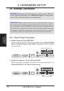
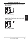
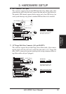
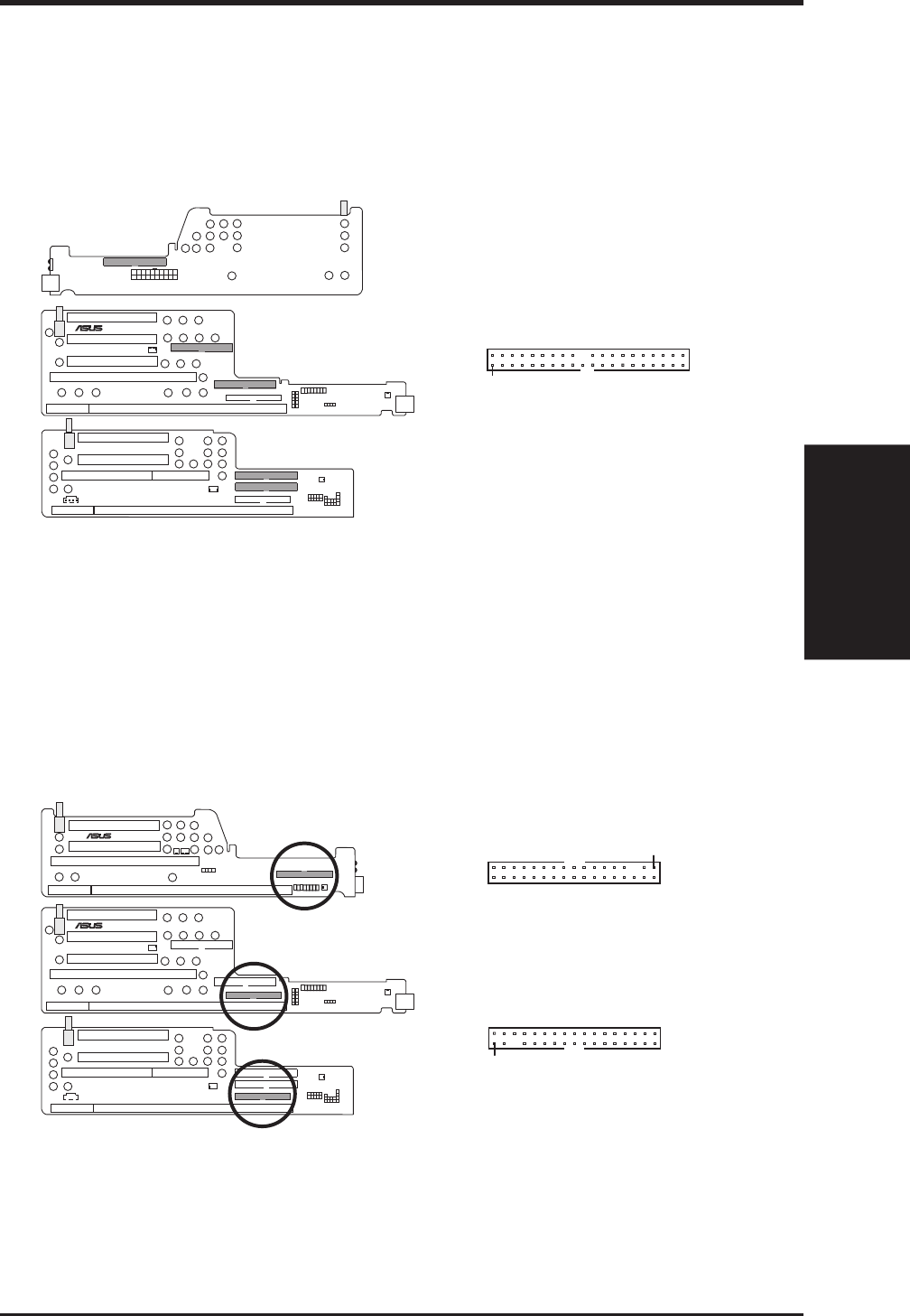
6) IDE Connectors (40-1 pins)
This connector supports the provided IDE hard disk drive ribbon cable. After
connecting one end to the riser card, connect the other end to a hard disk drive.
The primary IDE channel supports both a master and a slave IDE device, but
some system housings only permit a standard IDE hard drive to be installed.
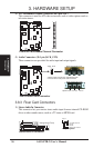
IDE Connectors
Orient the red stripe on the
IDE ribbon cable to Pin 1
Pin 1
®
B9-N
YEONG-YANG
NLX-R (Back)
B9-N (Front)
Yeong-Yang (Front)
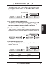
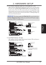
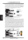
7) 3.5” Floppy Disk Drive Connector (34-1 pin FLOPPY)
This connector supports the provided floppy drive ribbon cable. After connect-
ing the single end to the riser card, connect the other end to a 3.5” floppy disk
drive. (Pin 5 is removed to prevent inserting in the wrong orientation when us-
ing ribbon cables with pin 5 plugged.)
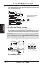
Floppy Disk Drive Connector
Orient the red stripe on the
floppy ribbon cable to Pin 1
Pin 1
NLX-R (Front)
B9-N (Front)
Yeong-Yang (Front)
®
NLX-R
®
B9-N
YEONG-YANG
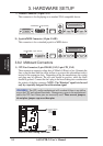
Pin 1
B9-N & Yeong-Yang Risers
NLX-R Riser