2-262-26
2-262-26
2-26
Chapter 2: Hardware informationChapter 2: Hardware information
Chapter 2: Hardware informationChapter 2: Hardware information
Chapter 2: Hardware information
2.7.22.7.2
2.7.22.7.2
2.7.2
Internal connectorsInternal connectors
Internal connectorsInternal connectors
Internal connectors
1.1.
1.1.
1.
Floppy disk drive connector (34-1 pin FLOPPY)Floppy disk drive connector (34-1 pin FLOPPY)
Floppy disk drive connector (34-1 pin FLOPPY)Floppy disk drive connector (34-1 pin FLOPPY)
Floppy disk drive connector (34-1 pin FLOPPY)
This connector is for the provided floppy disk drive (FDD) signal cable.
Insert one end of the cable to this connector, then connect the other
end to the signal connector at the back of the floppy disk drive.
Pin 5 on the connector is removed to prevent incorrect cable connection
when using a FDD cable with a covered Pin 5.
15.15.
15.15.
15.
Optical S/PDIF Out portOptical S/PDIF Out port
Optical S/PDIF Out portOptical S/PDIF Out port
Optical S/PDIF Out port. This port connects an external audio
output device via an optical S/PDIF cable. (
Deluxe model only
)
16.16.
16.16.
16.
Coaxial S/PDIF Out port.Coaxial S/PDIF Out port.
Coaxial S/PDIF Out port.Coaxial S/PDIF Out port.
Coaxial S/PDIF Out port. This port connects an external audio
output device via a coaxial S/PDIF cable.
17.17.
17.17.
17.
PS/2 keyboard port (purple).PS/2 keyboard port (purple).
PS/2 keyboard port (purple).PS/2 keyboard port (purple).
PS/2 keyboard port (purple). This port is for a PS/2 keyboard.
14.14.
14.14.
14.
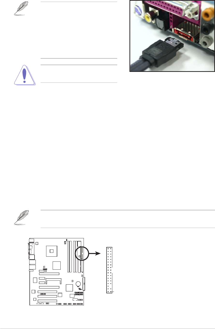
External SATA port.External SATA port.
External SATA port.External SATA port.
External SATA port. This port connects to an external SATA box
or a Serial ATA port multiplier. (
Deluxe model only
)
The external SATA port
supports external Serial ATA
1.5 and 3 Gb/s devices. Longer
cables support higher power
requirements to deliver signal
up to two meters away, and
enables improved hot-swap
function.
Do not insert a different
connector to this port.
P5ND2-SLI
®
P5ND2-SLI Series Floppy disk drive connector
gs
NOTE: Orient the red markings o
n
the floppy ribbon cable to PIN 1.
PIN 1
FLOPPY


