


ASUS RS700-E7/RS4 4-3
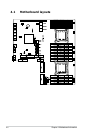
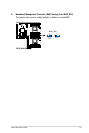
Layout contents
Jumpers Page
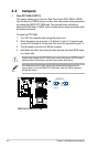
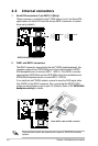
1. Clear RTC RAM (CLRTC1) 4-4
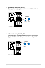
2. VGA controller setting (3-pin VGA_SW1) 4-5
3. LAN controller setting (3-pin LAN_SW1) 4-5
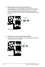
4. RAID conguration utility selection (3-pin RAID_SEL1) 4-6
5. ME rmware force recovery setting (3-pin ME_RCVR1) 4-6
Internal LEDs Page
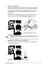
1. Standby power LED 4-13
2. CPU warning LED (ERR_CPU1, ERR_CPU2) 4-13
3. DIMM warning LED (ERR_DIMMA1-3, ERR_DIMMB1-3, ERR_
DIMMC1-3, ERR_DIMMD1-4, ERR_DIMME1-3,
ERR_DIMMF1-3, ERR_DIMMG1-3, ERR_DIMMH1-3)
4-14
4. BMC LED (BMC_LED)
4-14
Internal connectors Page
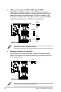
1. Serial ATA connectors (7-pin SATA1–2 [blue]) 4-8
2. ISAS1 and ISATA1 connectors 4-8
3. PSAS 1 and 2 connectors 4-9
4. Hard disk activity LED connector (4-pin HDLED1) 4-9
5. USB connectors (10-1 pin USB34, USB56, Type A USB10) 4-10
6. Serial port connectors (10-1 pin COM1) 4-10
7. System fan connectors (4-pin FAN1/2/3/4/5/6/7/8) 4-11
8. TPM connector (20-1 pin TPM1) 4-11