


KM0032 / KM0532 / KM0932 User Manual
10
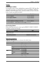
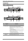
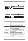
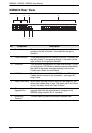
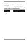
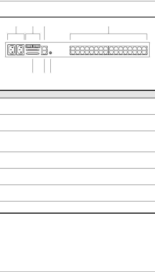
KM0032 Rear View
No. Component Description
1 Power Sockets The power cords from the AC source plug in here. The
socket on the left is Socket 1; the socket on the right is
Socket 2.
2 Power Switches These switches power the KM0032 on and off. The switch on
the left is Switch 1 and governs Socket 1; the switch on the
right is Switch 2 and governs Socket 2.
3 PON Port This connector is provided for a Power over the Net™ (PON)
unit to plug into. A PON device allows computers attached to
the switch to be power-managed remotely over the net.
Contact your dealer for more details.
4 KVM Ports The Cat 5e cables that link the KM0032 to the KVM Adapter
Cables (which connect to the computers – see page 18),
plug in here.
5 Daisy Chain Ports When daisy chaining KM0032 switches (see page 26), the
daisy chain cables plug in here. The upper port is the Chain
In port; the lower one is the Chain Out port.
6 Firmware
Upgrade Port
The firmware upgrade cable that transfers the firmware
upgrade data from the administrator's computer to the
KM0032, plugs into this RJ-11 connector.
7 Grounding
Ter min al
The wire used to ground the KM0032 attaches here.
31 24
5 6 7