AT91EB42 Evaluation Board User Guide 4-1
Section 4
Circuit Description
4.1 AT91M42800
Processor
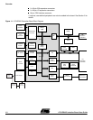
Figure 6-1 on page 6-2 shows the AT91M42800. The footprint is for a 144-pin TQFP
package.
Strap CB20 enables the user to choose between the standard ICE debug mode and the
JTAG boundary scan mode of operation.
The operating mode is defined by the state of the JTAGSEL input detected at reset.
Jumper JP5 (see Figure 6-8 on page 6-9 in Section 6, “Appendix B – Schematics”) can
be removed by the user to allow measurement of the current demand by the whole
microcontroller (V
DDIO
and V
DDCORE
). Jumper JP8 can be removed to measure the core
microcontroller consumption (V
DDCORE
).
4.2 Expansion
Connectors and
JTAG Interface
The two expansion connectors, I/O expansion connector and EBI expansion connector,
and the JTAG interface are described below.
The I/O and EBI expansion connectors’ pinout and position are compatible with the
other evaluation boards (except the I/O expansion connector pinout and position of the
EB40) so that users can connect their prototype daughter boards to any of these evalu-
ation boards.
4.2.1 I/O Expansion
Connector
The I/O expansion connector makes the general-purpose I/O (GPIO) lines, VCC3V3
and Ground, available to the user. Configuration straps CB2, CB3, CB4, CB11, CB13,
CB14, CB15, CB17, CB18 and CB19 are used to select between the I/O lines being
used by the evaluation board or by the user via the I/O expansion connector. The con-
nector is not fitted at the factory; however, the user can fit any 32 x 2 connector on a 0.1"
(2.54 mm) pitch.
4.2.2 EBI Expansion
Connector
The schematic (Figure 6-4 on page 6-5 in Section 6, “Appendix B – Schematics”) also
shows the bus expansion connector which, like the I/O expansion connector, is not fitted
at the factory. The user can fit any 32 x 2 connector on a 0.1" (2.54 mm) pitch to gain
access to the data, address, chip select, read/write, oscillator output and wait request
pins. VCC3V3 and ground are also available on this connector.
Configuration strap CB1, when open, allows the user to connect the EBI expansion con-
nector to the MPI expansion connector of an AT91EB63 evaluation board without any
conflicts.
4.2.3 JTAG Interface An ARM
®
-standard 20-pin box header (P5) is provided to enable connection of an ICE
interface to the JTAG inputs on the AT91. This allows code to be developed on the
board without using system resources such as memory and serial ports.


