


AT91EB42 Evaluation Board User Guide 5-1
Section 5
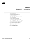
Appendix A – Configuration Straps
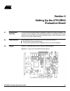
5.1 Configuration
Straps (CB1 - 23,
JP1 - 8)
By adding the I/O and EBI expansion connectors, users can connect their own peripher-
als to the evaluation board. These peripherals may require more I/O lines than available
while the board is in its default state. Extra I/O lines can be made available by disabling
some of the on-board peripherals or features. This is done using the configuration straps
detailed below. Some of these straps present a default wire (notified by the default men-
tion) that must be cut before soldering the strap.
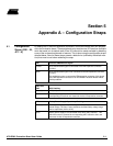
CB1 On-board PB5/A23/CS4 Signal
Closed
(1)
AT91 PB5/A23/CS4 signal is connected to the EBI expansion connector
(P1-B21).
Open AT91 PB5/A23/CS4 signal is not connected to the EBI expansion connector
(P1-B21).
This authorizes users to connect the EBI expansion connector of this board
to the MPI expansion connector of an AT91EB63 Evaluation Board without
conflict problems.
CB2, CB3,
CB4 ADC Enabling
Closed
(1)
ADC (U20) control lines enabled
Open ADC (U20) control lines disabled. This authorizes users to connect the
corresponding PIO to their own resources via the I/O expansion connector.
CB5 Battery Power Supply Supervisory Enabling
Closed
(1)
Battery power supply is supervised by the ADC (U20) channel 1 via a
resistor bridge. The ratio is set to 0.3333 so that the battery voltage range
can be supervised (5.5V to 6.2V).
Open Battery power supply is not connected to the ADC (U20) channel 1. This
authorizes users to connect the corresponding ADC channel to their own
resources via the I/O expansion connector.