


Setting Up the AT91EB42 Evaluation Board
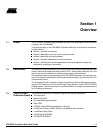
2-2 AT91EB42 Evaluation Board User Guide
2.4 Jumper Settings JP1 is used to boot standard or user programs. For standard operations, set it in the
STD position.
JP8 is used to select the core power supply of the AT91M42800: 3.3V or 1.8V. For oper-
ation at 1.8V, MCK frequency shall be limited to 17 MHz.
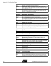
For more information about jumpers and other straps, see Section 5.
2.5 Powering Up
the Board
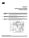
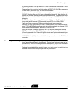
DC power is supplied to the board via the 2.1 mm socket (J1) shown in Figure 2-2. The
polarity of the power supply is not critical. The minimum voltage required is 7V.
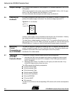
Figure 2-2. 2.1 mm Socket
A battery power supply can be connected to the board via the J3 connector. A battery
fast-charge controller is provided on-board to charge this battery.
The board has a voltage regulator providing +3.3V. The regulator allows the input volt-
age to range from 7
V to 9V. When you switch the power on, the red LED marked
POWER lights up. If it does not, switch off and check the power supply connections.
2.6 Measuring
Current
Consumption on
the AT91M42800
The board is designed to generate the power for the AT91 product, and only the AT91
product, through the jumper JP5 (V
DDIO
) and JP8 (V
DDCORE
). This feature enables mea-
surements to be made of the current consumption of the AT91 product.
See Section 5 for further details.
2.7 Testing the
AT91EB42
Evaluation Board
To test the AT91EB42 Evaluation Board, perform the following steps:
1. Hold down the SW1 button and power-up the board, or generate a reset and wait
for the light sequence on each LED to complete. All the LEDs light once and the
LED D1 remains lit.
2. Release the SW1 button. The LEDs D1 to D7 light up one after the other. If any
of the LEDs lights up twice, there is an error.
The LEDs represent the following components:
D1 for the internal RAM
D2 for the external RAM
D3 for the external Flash
D4 for the serial EEPROM
D5 for the SPI DataFlash
®
D6 for the EEPROM
D7 for the USART
D8 is reserved
If a test is not carried out, the corresponding LED remains unlit and the test sequence
restarts.
positive (+)
or
negative (-)
2.1 mm connector