


AT91EB42 Evaluation Board User Guide 6-1
Section 6
Appendix B – Schematics
6.1 Schematics The following schematics are appended:
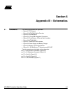
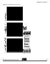
• Figure 6-1. PCB Layout
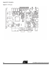
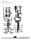
• Figure 6-2. AT91EB42 Blocks Overview
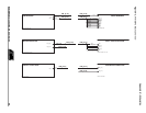
• Figure 6-3. EBI Memories
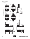
• Figure 6-4. I/O and EBI Expansion Connectors
• Figure 6-5. Push Buttons, LEDs and Serial Interface
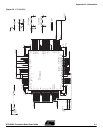
• Figure 6-6. AT91M42800
• Figure 6-7. Reset and JTAG Interface
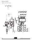
• Figure 6-8. Power Supply and Battery Charger
• Figure 6-9. Battery Type and Connection
• Figure 6-10. SPI Memories, I
2
C Memories and SPI ADC
The pin connectors are indicated on the schematics:
P1 = EBI Expansion Connector (Figure 6-4)
P2 = I/O Expansion Connector (Figure 6-4)
P3 = Serial A (Figure 6-5)
P4 = Serial B (Figure 6-5)
P5 = JTAG Interface (Figure 6-7)