


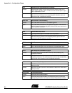

Appendix A – Configuration Straps
AT91EB42 Evaluation Board User Guide 5-3
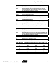
CB15 Serial DataFlash Enabling
Closed
(1)
AT91 NPCSA0 select signal is connected to the serial DataFlash memory.
Open AT91 NPCSA0 select signal is not connected to the serial DataFlash
memory. This authorizes users to connect the corresponding PIO to their
own resources via the I/O expansion connector.
CB17 SPI EEPROM Enabling
Closed
(1)
EEPROM communication enabled
Open EEPROM communication disabled. This authorizes users to connect the
corresponding PIO to their own resources via the I/O expansion connector.
CB18 PB20 ADC Write Access Signal
Closed
(1)
AT91 PB20 signal is used to control the RD/WR ADC (U20) input pin. Prior to
a write access, position this PIO line in a low state. Position it in a high state
prior to a read access.
Open AT91 PB20 signal is not used to control the RD/WR ADC (U20) input pin.
This authorizes users to connect the corresponding signal to their own
resources via the I/O expansion connector.
CB19 PB18 End of Fast Charge Signal
Closed
(1)
AT91 PB18 signal is connected to the battery charger (U16), NFASTCHG
output pin.
Open AT91 PB18 signal is not connected to the battery charger (U16), NFASTCHG
output pin. This authorizes users to connect the corresponding signal to their
own resources via the I/O expansion connector.
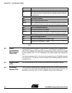
CB20 JTAGSEL
1-2
(1)
AT91 standard ICE debug feature enabled
2-3 IEEE 1149.1 JTAG boundary scan feature enabled
CB21, CB22, CB23 Charger Device (U16): Programming the Battery Number of Cells
Number of Cells CB21 CB22 CB23
1 Open Closed Closed
2 Open Open Closed
4 Closed Open Closed
5
(1)
Open Closed Open
6 Open Open Open
8 Closed Open Open