


Ref.:
UoD_SpW-10X_
UserManual
Issue:
3.4
SpW-10X
SpaceWire Router
User Manual
Date:
11
th
July 2008
Preliminary
133
10.6 LATENCY AND JITTER
The timing parameters for the data and time-code latency and the time-code jitter are derived from the
receive clock, transmit clock and system clock period. The worst case number of clock cycles required
is used in each equation.
In the SpaceWire router the system clock is a known frequency and the transmitter and receiver
frequency are derived from the input and output bit rates. The clock frequencies are defined as
follows.
Note: All figures are worst case. Due to the uncertainty of synchronisation between clock domains the
measured time may be less than indicated.
In the following sections the clock periods are defined and the latency and jitter timing parameter
definitions are detailed.
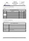
10.6.1 Clock Periods
System Clock Period
T
SYSPERIOD
= 33.333 ns (Clock Frequency = 30 MHz)
Transmit Clock Period
T
TXPERIOD
= Transmit bit rate period * 2 (Where Transmit bit rate period is the output bit rate selected
by the user configuration)
Receive Clock Period
T
RXPERIOD
= Receive bit rate period * 2 (Where Receive bit rate period is the period of the input bit rate)
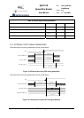
10.6.2 Switching Latency
Switching latency is the time it takes the router to connect a waiting input port to an output port that
has just finished sending a packet. It includes any time for group adaptive routing and arbitration of
two or more input ports competing for the same output port.
Switching latency for the router is defined as follows
SYSPERIODSWITCH TT ×= 4
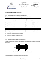
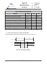
10.6.3 Router Latency
Router latency is the time taken for a character in a packet to pass through the router assuming that
the packet has already been switched to an output port and that there is no blocking of the output port.
Router latency for the SpaceWire router is defined for port to port data transfer operations as follows: