


Ref.:
UoD_SpW-10X_
UserManual
Issue:
3.4
SpW-10X
SpaceWire Router
User Manual
Date:
11
th
July 2008
Preliminary
82
3.3V
2850Ω 20kΩ
R
T
=100Ω
16kΩ
Vdd
2850Ω
91µA 87µA 12µA
99µA
190µA
3.05V
3.04V
10mV
‐
+
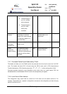
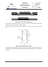
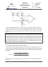
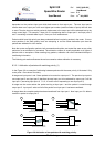
Figure 8-3 Deactivated LDVS driver output connected to external bias network on LVDS input
Current can now flow from the 3.3 volt supply to ground. When the bias resistors for 10mV noise
margin are used, the total current flowing out of the LVDS outputs is around 200 µA as illustrated in
Figure 8-3
WARNING
The deactivate mode (see also section 9.4.3) does not tri-state the LVDS outputs. The LVDS outputs
are cold-sparing and when disabled both outputs in an LVDS differential pair are pulled up to 3.3V and
have an impedance of the order of 1 kohm. Since they are differential outputs and are both are at the
same voltage no current will flow. If, however, external noise bias resistors are being used then a
small current (around 200 µA, 0.7 mW power) can flow. This is substantially less than the normal
operating current of LVDS outputs and hence saves power.
8.1.6 Setting the SpaceWire port transmit data rate
The SpaceWire port transmit data rate is dependent on the input signal FEEDBDIV (See section 5.1),
the PLL output clock divider value TXDIV (See section 9.5.9) and the data rate divider value TXRATE
in each SpaceWire link control register (See section 9.4.3). The resultant data rate is determined by
the function.
()
(
)
2*
1
2
*20100
1
⎟
⎟
⎟
⎟
⎠
⎞
⎜
⎜
⎜
⎜
⎝
⎛
+
⎟
⎠
⎞
⎜
⎝
⎛
+
=
+
TXRATE
FEEDBDIVMHzMHz
DataRate
TXDIV
The output of the PLL is also used to provide the 10 Mbits/s transmit clock used during SpaceWire link
initialisation.