


Ref.:
UoD_SpW-10X_
UserManual
Issue:
3.4
SpW-10X
SpaceWire Router
User Manual
Date:
11
th
July 2008
Preliminary
46
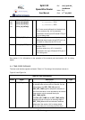
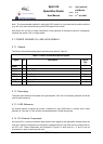
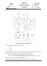
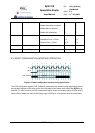
Figure 5-3 PLL with external components
The PLL loop filter component values to be used are
R = 10 kΩ
C = 120 pF
C0 = 3.3 pf.
The VCO bias resistor depends on the required VCO frequency range which is determined by the PLL
feedback divider (NF in Figure 5-3). The VCO bias resistor values to use are
Rvco = 4.7 kΩ for 100-150MHz (FEEDBDIV = 0b000, 0b001, or 0b010),
Rvco = 1.8 kΩ for 150MHz-200MHz (FEEDBDIV = 0b011, 0b100, 0b101 or 0b110, or 0b111).
See section 5.1 for information about the FEEDBDIV inputs.
A dedicated decoupling capacitors (100 nF and 1µF) are required for the PLL power supply.