


Ref.:
UoD_SpW-10X_
UserManual
Issue:
3.4
SpW-10X
SpaceWire Router
User Manual
Date:
11
th
July 2008
Preliminary
32
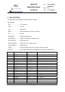
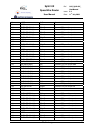
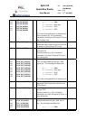
Table 5-1 Global Signals
PinNo Signal Dir Description Type
2
CLK
In System clock. Provides the reference clock for all
modules except the interface receivers.
CMOS3V3
3
RST_N
In Asynchronous system reset (active low). CMOS3V3
4
TestIOEn
In ASIC Test control signal; Shall be connected to
logic ‘0’ during normal operation.
Tie to ground.
CMOS3V3;
Internal pull-down
5
TestEn
In ASIC Test control signal; Shall be connected to
logic ‘0’ during normal operation.
Tie to ground.
CMOS3V3;
Internal pull-down
10
9
6
FEEDBDIV(2)
FEEDBDIV(1)
FEEDBDIV(0)
In Set the output clock rate of the internal PLL as
follows:
“000” Æ 100MHz
“001” Æ 120MHz
“010” Æ 140MHz
“011” Æ 160MHz
“100” Æ 180MHz
“101” Æ 200MHz
“110” Æ 200MHz
“111” Æ 200MHz
See section 8.1.6 for setting the transmit rate.
CMOS3V3;
Internal pull-down
See section 10.1 for timing details.
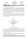
WARNING
Simultaneous data/strobe transitions can occur during reset and power up. This is not a problem when
connected to SpaceWire compliant devices but is a problem when connected to IEEE-1355 devices.
5.2 SPACEWIRE SIGNALS
5.2.1 SpW-10X SpaceWire Signals
The SpaceWire interface signals are listed in Table 5-2. For further details about SpaceWire see the
SpaceWire standard [AD1]. The LVDS inputs and outputs are cold sparing [RD3].