


Ref.:
UoD_SpW-10X_
UserManual
Issue:
3.4
SpW-10X
SpaceWire Router
User Manual
Date:
11
th
July 2008
Preliminary
21
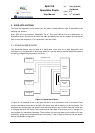
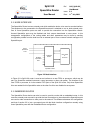
3. FUNCTIONAL OVERVIEW
A SpaceWire routing switch comprises a number of SpaceWire ports and a routing matrix. The routing
matrix enables packets arriving at one SpaceWire port to be transferred to and sent out of another port
on the routing switch. A SpaceWire routing switch is thus able to connect together many SpaceWire
nodes, providing a means of routing packets between the nodes connected to it.
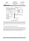
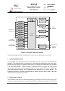
The SpW-10X SpaceWire router comprises the following functional logic blocks:
• Eight SpaceWire bi-directional serial ports.
• Two external parallel input/output ports each comprising an input FIFO and an output FIFO.
• A crossbar switch connecting any input port to any output port.
• An internal configuration port accessible via the crossbar switch from the external parallel
input/output port or the SpaceWire input/output ports.
• A routing table accessible via the configuration port which holds the logical address to output
port mapping.
• Control logic to control the operation of the switch, performing arbitration and group adaptive
routing.
• Control registers than can be written and read by the configuration port and which hold control
information e.g. link operating speed.
• An external time-code interface comprising tick_in, tick_out and current tick count value.
• Internal status/error registers accessible via the configuration port.
• Watchdog timers on all ports.
• Internal status/error registers accessible via the configuration port using the RMAP protocol
[2].
• External status/error signals.
A block diagram of the routing switch is given in Figure 3-1.