


Ref.:
UoD_SpW-10X_
UserManual
Issue:
3.4
SpW-10X
SpaceWire Router
User Manual
Date:
11
th
July 2008
Preliminary
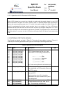
41
172
171
170
EXT_TIME_OUT(2)
EXT_TIME_OUT(1)
EXT_TIME_OUT(0)
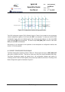
falling edge of EXT_TICK_OUT. The
EXT_TIME_OUT(7:0) value is held until the next
time-code is output.
See section 6.2 for information on the operation of the time-code interface and section 10.4 for timing
details.
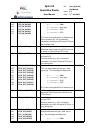
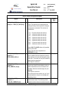
5.5 STATUS INTERFACE SIGNALS
The status interface signals are listed in Table 5-5.
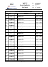
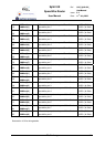
Table 5-5 Link error indication Signals
PinNo Signal Dir Description Signal
Type
183
182
181
180
STAT_MUX_ADDR(3)
STAT_MUX_ADDR(2)
STAT_MUX_ADDR(1)
STAT_MUX_ADDR(0)
in Select the error indication status signals to be
output on STAT_MUX_OUT as defined in
Table 6-1.
These inputs should be driven or pulled up or
down (e.g. 4k7 Ω) depending on what
information is required from the status outputs.
CMOS3V3
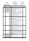
195
194
193
192
191
188
187
186
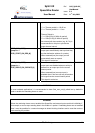
STAT_MUX_OUT(7)
STAT_MUX_OUT(6)
STAT_MUX_OUT(5)
STAT_MUX_OUT(4)
STAT_MUX_OUT(3)
STAT_MUX_OUT(2)
STAT_MUX_OUT(1)
STAT_MUX_OUT(0)
inout Multi function pin.
Power on Configuration
After reset the STAT_MUX_OUT pins are
inputs which define the power on configuration
status of the router. The pin mappings are
listed in section 5.6.
These pins should be pulled up or down (e.g.
4k7 Ω) to provide the required power on
configuration input values.
Normal Operation
After the power on reset configuration of the
router has been read from STAT_MUX_OUT
the pins are driven as outputs by the router.
The function of these output pins is defined by
STAT_MUX_ADDR(3:0). Further details are
given in section 6.3.
CMOS3V3