


Location and Functions of Control
2-1
5975597 BARCODATA 808S 110397
2
LOCATION AND FUNCTION OF CONTROLS
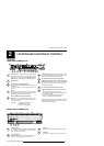
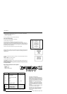
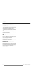
REAR PANEL TERMINOLOGY
PORT 4/5
See installation instructions before connecting to the supply.
Voir la notice d'installation avant de raccorder au réseau.
120/ 230 V
7/5 Amp
50/60 Hz
75 Ohm
PORT 2
75 Ohm
1 2 3 4 5 76 8 9
10
This device comp lies wi th part 15 of
the F CC rules. Oper ation is sub ject t o
following two conditions (1). This
devic e may no t cau se har mful i nt er-
feren ce, an d ( 2) th is d evice mu st
accep t an y in terf eren ce re ceived
incl udin g i nterf ere nce tha t m ay cause
undesired operation"
Power Switch : Press the switch to turn the projector ON.
Depending on the hardware set-up of the projector during
installation, the projector switches to ‘Standby’ or to ‘Op-
erational' mode. If in standby, the standby LED lights up.
AC Power Input
Communication Port (800 peripherals)
* Allows communication between the RCVDS switcher and
the projector.
* Allows connection of a remote IR receiver unit to the
projector.
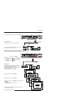
Port 3
RGB Analog Input (9 pin female sub D connector). Allows
a character generator, microcomputer, etc. having analog
RGB outputs to be connected to the projector.
Port 4/5 : RGB-S Input (5x BNC connector):
RGB-S input : allows a character generator, microcomputer,
video camera, etc. having analog RGB output to be con-
nected to the projector.
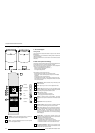
Line inputs: - signals RED-GREEN-BLUE
- COMPOSITE sync. signal
- Tri level sync signal (option)
1
2
S-VIDEO Input: Separated Y/C (luma-chroma) signal in-
puts and outputs for higher quality playback of Super VHS
signals (4-pin S-VIDEO connector loop-through).
75 ohm Termination Switch for S-Video signals
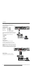
VIDEO Input (Composite video, 2x loop-through BNC
connector): Allows a video tape recorder, video camera,
color receiver/monitor, etc. having video line output to be
connected to the projector.
75 ohm Termination Switch for Video signals
Projector Pilot Lamp : Indicates the status of the projector.
- Unlit : mains (power) switch is not pressed.
- Lit : mains (power) switch is pressed and the indicated color
shows the projector mode:
Green color : Operational mode of the projector.
Red color : Standby mode of the projector.
Important : Projector ("Operational" or "Standby") mode is
defined during the installation of the projector. (Refer to a
qualified technician for change).
3
4
5
6
7
8
9
10
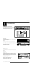
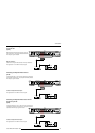
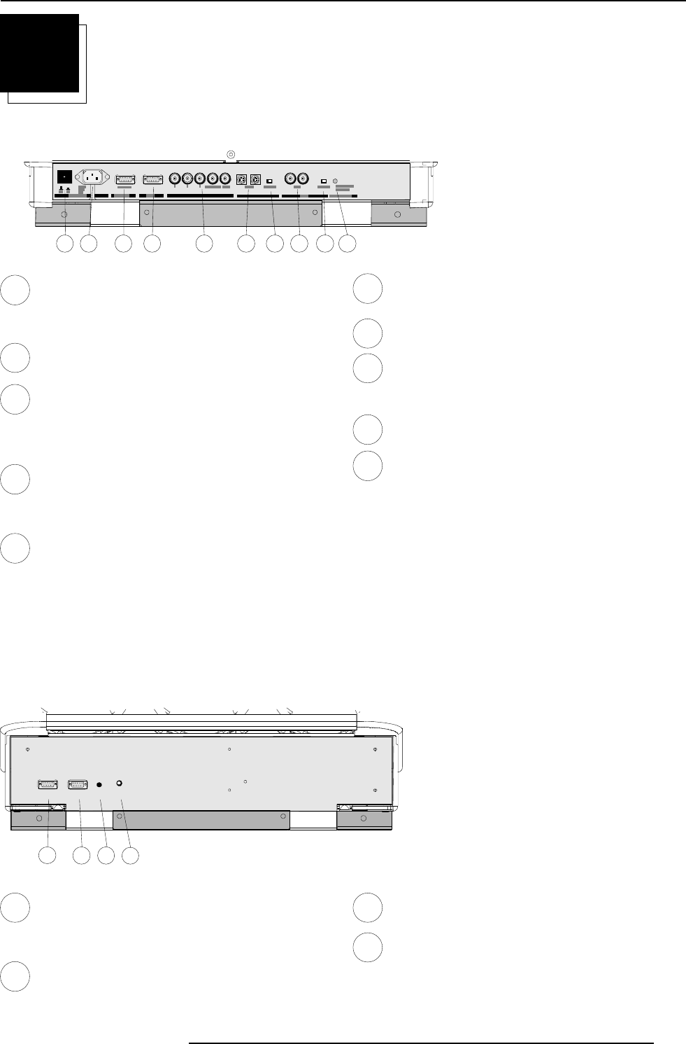
FRONT PANEL TERMINOLOGY
RS232 IN
RS232 OUT IR
REMOTE
RS232 INRS232 OUTIR
REMOTE
11
12 13
14
RS 232 Input Port
Connection between the BARCODATA 808 and an IBM PC
(or compatible) or MAC (RS422) for remote computer
control and data communication.
RS 232 Output Port
RS 232 Output Port allows a communication link for PC or
MAC to the next projector in a series of projector.
IR Sensor
Receiver for control signals transmitted from the RCU.
IR Remote
Connector for remote input for hard wired remote control
11
12
13
14