


4. Connections
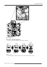
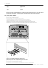
4.5.4 Fixed slot (slot 1 & 2)
Where to find?
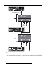
Slot 1 & 2 has 5 BNC input terminals for 5 cable input and a DVI plug for DVI input. Slot 1 has also an DVI output for loop through
to a second projector. Within the installation mode it is possible to setup the input for 5 cable or DVI (PanelLink).
Which signals can be connected to slot 1 & 2?
Connector name/
Input signal
R
G
B H V
RGBHV
R
G
B H V
RGBS
R
G
B
S
-
RGsB
R
Gs
B
- -
Composite Video
-
Video
- - -
Super Video
-
Y
- -
C
Component Video — SS
R-Y Y B-Y
S
-
Component Video — SOY
R-Y Ys B-Y
- -
DVI signals can be connected to the DVI input connector.
Pin assignment for the DVI connector.
Pin 1
TMDS DATA2-
Pin 13
TMDS DATA3+
Pin 2
TMDS DATA2+
Pin14 +5Power
Pin 3
TMDS DATA2/4 Shield
Pin 15
Ground (for +5V)
Pin 4
TMDS DATA4-
Pin 16 Hot Plug Detect
Pin 5
TMDS DATA4+
Pin 17
TMDS DATA0-
Pin 6
DDC Clock
Pin 18
TMDS DATA0+
Pin 7
DDC Data
Pin 19
TMDS DATA0/5 Shield
Pin 8 No connect Pin 20
TMDS DATA5-
Pin 9
TMDS DATA1-
Pin 21
TMDS DATA5+
Pin 10
TMDS DATA1+
Pin 22
TMDS Clock Shield
Pin 11
TMDS DATA1/3 Shield
Pin 23
TMDS Clock+
Pin 12
TMDS DATA3-
Pin 24
TMDS Clock-
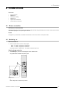
How to select input slot 1 or 2 ?
1. Key in 1 or 2 on the RCU or the local keypad.
How to change the input slot setting?
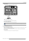
1. Press ADJUST or ENTER key to start up the Adjustment mode.
2. Pus
h the cursor key ↑ or ↓ to select Installation.
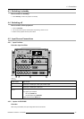
ADJUSTMENT MODE
Select a path from below :
RANDOM ACCESS
INSTALLATION
SERVICE
Select with ↑ or ↓
then <ENTER>
<EXIT> to return
Menu 4-4
R5976654 SLM R12+ 27/01/2005 37