


DS72 Host Module
17
Parity
Parity is a simple form of error checking used in serial communication. For even and odd parity, the
serial port will set the parity bit (the last bit after the data bits) to a value to ensure that the transmission
has an even or odd number of logic high bits. For example, if the data was 011, then for even parity,
the parity bit would be 0 to keep the number of logic high bits even. If the parity was odd, then the
parity bit would be 1, resulting in 3 logic high bits. This allows the receiving device to know the state
of a bit so as to enable the device to determine if noise is corrupting the data or if the transmitting and
receiving devices' clocks are out of sync.
With no parity selected (or defaulted), it's assumed that there are other forms of checking that will
detect any errors in transmission. No parity also usually means that the parity bit can be used for data,
speeding up transmission. In modem-to-modem communication, the type of parity is coordinated by
the sending and receiving modems before the transmission takes place.
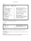
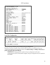
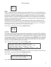
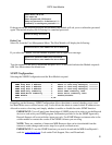
Select “Parity” the DS displays the following: Default is None.
Xon/Xoff
For a simple communication between modems three connected lines are needed: TX, Rx, and Ground.
For the data to be transmitted, both sides have to be clocking the data at the same baud rate. While this
method is sufficient for most applications, it is limited in being able to respond to problems such as the
receiver getting overloaded. This is where serial handshaking can help. Xon/Xoff is software data flow
communications protocol for controlling the flow of data between Baytech and other devices. Baytech
units will send an XOFF character when it can't take any more data and when it can once again take
more data, will send an XON character to the transmitter.
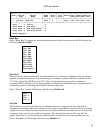
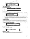
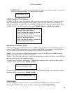
Select “Xon/Xoff” the DS displays the following, Default is Off:
RTS/DTR Line Driver Inactivity State
RTS (Request to Send)/ DTR (Data Terminal Ready) is normally used in conjunction with an external
modem. With no modem the RTS and DTS default state is Low.
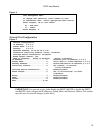
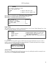
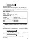
Select “RTS Driver State” the DS displays the following:
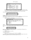
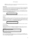
Select “DTR Driver State” the DS displays the following:
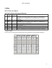
1 For 1
2 For 1-1/2
3 For 2
1 For None
2 For Even
3 For Odd
Output Flow Control (Xmit) - Xon/Xoff is ( Off )
Stop/Restart Output Upon Receiving of Xoff/Xon ? (Y/N) :
Output Flow Control (Recv) - Xon/Xoff is ( Off )
Xoff/Xon sent based on Buffer - Full/Empty Condition ? (Y/N) :
RTS Line Driver Inactive State is: Low
High ? (Y/N, CR for no change):