


8 485SDA103798 Manual
B&B Electronics -- 707 Dayton Rd. -- PO Box 1040 -- Ottawa, IL 61350
PH (815) 433-5100 -- FAX (815) 434-7094
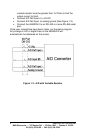
Digital I/O Connections
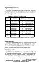
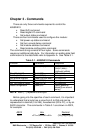
The digital I/O connections are made on the I/O port, which is a
DB-25S (female) connector. Table 2.1 shows the pinout of the I/O
port. The next sections explain the functions and connections for
the various digital signals.
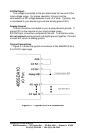
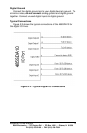
Digital Inputs #0-2
The digital input lines are CMOS/TTL compatible and can handle
voltages from -30V DC to +30V DC. If a digital input is from -30V
DC to 1.0V DC, the state will be read as a “0” (LOW). If a digital
input is from 2.0V DC to 30V DC, the state will be read as a “1”
(HIGH). Connect unused digital inputs to digital ground.
Digital Outputs #0-2
The digital output lines are CMOS/TTL compatible. A digital
output that is set to a “0” (LOW) will output a voltage from 0 to 0.6V
DC. A digital output that is set to a “1” (HIGH) will output a voltage
from 4.3V DC to 5.0V DC. Refer to Chapter 1, Specifications, for
more information. Unused digital output lines should be left open.
Table 2.1 - 485SDA10 I/O Port Pinout
DB-25S
Pin # Function
DB-25S
Pin # Function
1 GND 14 Digital Output #0
2 +12V DC Output* 15 Digital Output #1
3 Digital Input #0 16 Digital Output #2
4 Digital Input #1 17 +5V DC Output
5 Digital Input #2 18 A/D Ref. Input +
6 Digital GND 19 A/D Ref. Input -
7 Analog GND 20 No connection
8 A/D Input #0 21 A/D Input #6
9 A/D Input #1 22 A/D Input #7
10 A/D Input #2 23 A/D Input #8
11 A/D Input #3 24 A/D Input #9
12 A/D Input #4 25 A/D Input #10
13 A/D Input #5
*Actual output is equal to power supply input minus 0.7V DC