


12 485SDA103798 Manual
B&B Electronics -- 707 Dayton Rd. -- PO Box 1040 -- Ottawa, IL 61350
PH (815) 433-5100 -- FAX (815) 434-7094
Chapter 3 - Commands
There are only three commands required to control the
485SDA10:
• Read A/D command
• Read digital I/O command
• Set output states command
There are four commands used to configure the module:
• Set power-up states command
• Set turn-around delay command
• Set module address command
• Read module configuration command
The command string consists of four bytes. Some commands
require an additional data byte. For information on adding data field
confirmation to the data fields refer to Appendix A. See Table 3.1.
Before going into the specifics of each command, it is important
to understand that a byte has a value from 0 to 255 and can be
represented in decimal (0 to 255), hexadecimal (00 to FF), or by an
ASCII character. The commands in Table 3.1 are shown in ASCII,
for example:
ASCII
!0RD
Hex
<21><30><52><44>
Decimal
(33)(48)(82)(68)
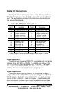
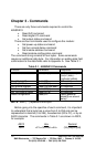
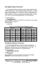
Table 3.1 - 485SDA10 Commands
Function Command Response
Read A/D Channels !{addr}RA{#} {ch#msb}{ch#lsb}
{ch(#-1)msb}...
{ch0msb}{ch0lsb}
Read Digital I/O !{addr}RD {I/O states}
Set Output States !{addr}SO{#} no response
Set Module Address !{addr}SA{new addr} no response
Set Power-up States !{addr}SS{#} no response
Set Turn-around Delay !{addr}SC{#} no response
Read Configuration !{addr}RC {addr}{powerup
states}{turn-around
delay}
NOTE: Each {...} represents one byte.