


485SDA103798 Manual 27
B&B Electronics -- 707 Dayton Rd. -- PO Box 1040 -- Ottawa, IL 61350
PH (815) 433-5100 -- FAX (815) 434-7094
‘ Clear bit 2 of states to make digital output 2 LOW
states = states AND (NOT(4))
Command$ = “!” + CHR$(addr) + “SS” + CHR$(states)
Print #1, Command$
At power-up digital output 0 will be HIGH, digital output 1 will
be HIGH, and digital output 2 will be LOW.
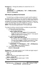
Set Turn-around Delay
The Set Turn-around Delay command sets the amount of time
the 485SDA10 waits to respond after executing a command. This
delay is necessary when two RS-485 transmitters are sharing a pair
of wires to ensure that two transmitters are not enabled at the same
time. Refer to B&B Electronics’ free RS-422/RS-485 Application
Note for more information on RS-422/485. The turn-around delay is
stored in non-volatile memory. This command requires a data byte.
The data byte is used to specify the turn-around delay. One unit of
turn-around delay is equal to the transmission time of one character.
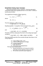
This transmission time can be computed as follows:
time = (1 / baud rate) * 10
The steps to setting a module’s turn-around delay are given below:
1) Constructing the command string:
Command$ = “!” + CHR$(addr) + “SC” + CHR$(delay)
Where addr is the module’s address and delay is the turn-
around delay. Refer to Chapter 3 for more information on
turn-around delay.
2) Transmitting the command string:
Print #1, Command$
Example 5.6 – Set the turn-around delay on the module with
address 5 to 100 character transmission times.
addr = 5
delay = 100
Command$ = “!” + CHR$(addr) + “SC” + CHR$(delay)
Print #1, Command$
The module at address 5 will now have a turn-around delay of
100 character transmission times.