


485SDA103798 Manual Appendix A A-1
B&B Electronics -- 707 Dayton Rd. -- PO Box 1040 -- Ottawa, IL 61350
PH (815) 433-5100 -- FAX (815) 434-7094
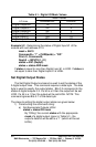
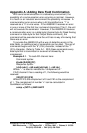
Appendix A: Adding Data Field Confirmation
With serial communications in a laboratory environment, the
possibility of a communication error occurring is minimal. However,
in a harsh or an industrial environment the possibility increases. A
communication error occurs when a bit transmitted as a “1” is
received as a “0” or vice versa. If the 485SDA10 receives an error
in one or more of the first four command characters (“!0xx”), the unit
will not execute the command. However, if the 485SDA10 receives
a communication error on a data byte (channel byte for Read Analog
command or state byte for Set Output State command), the
command will be executed since the unit has no way of knowing that
there was an error.
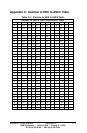
To provide the 485SDA10 with a way of detecting errors in the
data fields, an additional set of commands can be used. This set of
commands begins with the “#” (23h) character, instead of the “!”
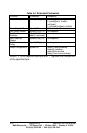
(21h) character. Refer to Table A-1. With these commands every
data byte that is transmitted or received is followed by its
complement.
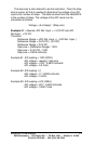
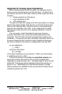
Example A.1 - To read A/D channel zero:
Command syntax:
#{addr}RA{00}{FF}
Response syntax:
{ch0 msb}{~ ch0 msb}{ch0 lsb} {~ ch0 lsb}
Where “~” is used to indicate the “complement of.”
If A/D channel 0 has a reading of 1, the following would be
received:
{00}{FF}{01}{FE}
Where FFh is the complement of 0 and FEh is the complement
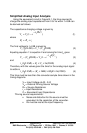
of 1. The complement of number “x” can be calculated in
QuickBasic as follows:
comp = (NOT x) AND &HFF