


26 485SDA103798 Manual
B&B Electronics -- 707 Dayton Rd. -- PO Box 1040 -- Ottawa, IL 61350
PH (815) 433-5100 -- FAX (815) 434-7094
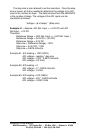
Example 5.4 – Change the address of a model from 5 to 10.
addr = 5
newaddr = 10
Command$ = “!” + CHR$(addr) + “SA” + CHR$(newaddr)
Print #1, Command$
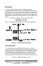
Set Power-up States Command
The Set Power-up States command is used to set the states of
the digital outputs at power-up. This command requires a data byte.
The data byte is used to specify the power-up output states. Bits 0-2
correspond to the power-up states of digital outputs 0-2. If a bit is a
0 then the output will be set LOW at power-up. If a bit is a 1 then the
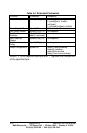
output will be set HIGH at power-up. Refer to Table 3.6.
NOTE: This command ignores bits 3-7 of the data byte.
The steps to setting a module’s power up states are given below:
1) Construct the command string:
a) Set appropriate outputs HIGH
states = states OR mask
By “ORing” the current states with the appropriate
mask of a digital output given in Table 5.1, the output’s
data bit will be set to a “1” (HIGH).
b) Set appropriate outputs LOW
states = states AND (NOT(mask))
By “ANDing” the current states with the complement of
the appropriate mask of a digital output given in Table
5.1, the output’s data bit will be set to a “0” (LOW).
c) Construct the string
Command$ = “!” + CHR$(addr) + “SS” + CHR$(states)
Where addr is the module’s address.
2) Transmitting the command string:
Print #1, Command$
Example 5.5 – Set digital outputs 0 and 1 HIGH and digital output 2
LOW on the module with address 5.
addr = 5
states = 0
‘ Set bit 0 of states to make digital output 0 HIGH
states = states OR 1
‘ Set bit 1 of states to make digital output 1 HIGH
states = states OR 2