


10 485SDA103798 Manual
B&B Electronics -- 707 Dayton Rd. -- PO Box 1040 -- Ottawa, IL 61350
PH (815) 433-5100 -- FAX (815) 434-7094
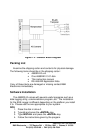
Serial Port Connections
To communicate with the 485SDA10 module, it must be
connected to an RS-422/RS-485 serial port. The 485SDA10 works
with 2-wire or 4-wire RS-485. The unit automatically detects baud
rates from 1200 to 9600. A data format of 8 data bits, 1 stop bit and
no parity is used. Connections are made using terminal blocks.
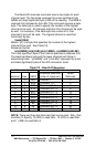
Table 2.2 shows the terminal blocks and their functions.
Table 2.2 - RS-485 Terminal Block Connections
TB
Label Signal
485SDA1
0 Function Notes
TD(A) Transmit Data (A) Output Connection is required. [Loop
to RD(A) for 2-wire hookup]
TD(B) Transmit Data (B) Output Connection is required. [Loop
to RD(B) for 2-wire hookup]
RD(A) Receive Data (A) Input Connection is required. [Loop
to RD(A) for 2-wire hookup]
RD(B) Receive Data (B) Input Connection is required. [Loop
to RD(B) for 2-wire hookup]
GND Ground - Connection for Signal GND
and Power Supply GND.
+12V +12 V DC Power Input Connection is required.
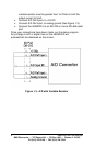
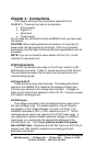
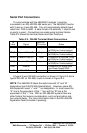
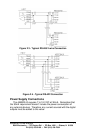
A typical 2-wire RS-485 connection is shown in Figure 2.3 and a
typical RS-422 (or RS-485) 4-wire is shown in Figure 2.4.
NOTE: The 485SDA10 labels the data lines with “A” and “B”
designators (per EIA RS-485 Specification). However, some RS-
485 equipment used “+” and “-“ as designators. In most cases the
“A” line is the equivalent of the “-“ line and the “B” line is the
equivalent of the “+” line. With an RS-485/422 system there are
other factors that require consideration, such as termination and
turn-around delay. For more information refer to the RS-485/422
Application Note (included in packing).