


485SDA103798 Manual 25
B&B Electronics -- 707 Dayton Rd. -- PO Box 1040 -- Ottawa, IL 61350
PH (815) 433-5100 -- FAX (815) 434-7094
b) Set Appropriate Outputs LOW
states = states AND (NOT(mask))
By “ANDing” the current states with the complement of
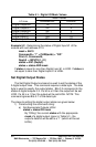
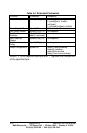
the appropriate mask of a digital output (given in Table
5.1), the output’s data bit will be set to a “0” (which will
be set LOW).
c) Construct the string
Command$ = “!0SO” + CHR$(states)
2) Transmitting the command string:
Print #1, Command$;
Example 5.3 - Set Digital Output #0 HIGH and Digital Output #2
LOW of the module with and address of 5.
addr = 5
‘ Set bit 0 of states to make Digital Output #0 HIGH
states = states OR 1
‘ Clear bit 2 of states to make Digital Output #2 LOW
states = states AND (NOT(4))
Command$ = “!” + CHR$(addr) + “SO” + CHR$(states)
Print #1, Command$;
Digital Output #0 will be set HIGH. Digital Output #2 will be set LOW.
Digital Output #1 will not change. Note that the variable states is
assumed to be value from Example 5.2.
Set Module Address
The Set Module Address command is used to change the
address of a 485SDA10. This command requires a data byte. The
data byte is used to specify the new address of the unit. The
address of a module is stored in non-volatile memory.
The steps to setting a module address are given below:
1) Constructing the command string:
Command$ = “!” + CHR$(addr) + “SO” + CHR$(newaddr)
Where {addr} is the current address of the module and
{new address} is a byte representing the new address.
2) Transmitting the command string:
Print #1, Command$