


Manual Documentation Number: RT-12 series-4006m 13
B&B Electronics Mfg Co Inc – 707 Dayton Rd - PO Box 1040 - Ottawa IL 61350 - Ph 815-433-5100 - Fax 815-433-5104 – www.bb-elec.com
B&B Electronics – Westlink Commercial Park – Oranmore, Galway, Ireland – Ph +353 91-792444 – Fax +353 91-792445 – www.bb-europe.com
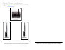
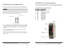
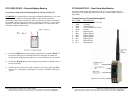
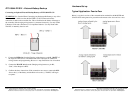
RT12-4444-9T-W20 – External Battery Back-up
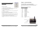
Connecting an Optional External Backup Battery to RT12-4444-9T-W20
!WARNING: Use Caution When Connecting Any Rechargeable Battery to any
of the RT series RTU’s. Make sure that the BATTERY is NOT connected until
the connection is made to the controller first. This will minimize the chance of
damage to the controller if the charging wiring harness is connected incorrectly.
Use only Nickel Cadmium 12Vdc and a minimum of 1.5 Amp Hour batteries.
Use only fused cable. The RTU is internally fused as well.
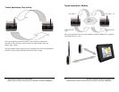
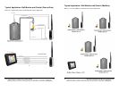
1) Connect the RED wire from the Charging wiring harness to pin 19, “BATT”
of the respective RTU device. The Master and Slave controllers are identical
in wiring, features and programming. Be sure a 1 Amp FAST blow fuse is
installed.
2) Connect the BLACK wire from the Charging wiring harness to pin 20,
,“Gnd”, of the respective device.
3) Confirm the above instructions. If the connections are correct, connect the
RED wire to the (+) of the battery and the black wire to the (-). The RTU will
begin to operate.
14 Manual Documentation Number: RT-12 series-4006m
B&B Electronics Mfg Co Inc – 707 Dayton Rd - PO Box 1040 - Ottawa IL 61350 - Ph 815-433-5100 - Fax 815-433-5104 – www.bb-elec.com
B&B Electronics – Westlink Commercial Park – Oranmore, Galway, Ireland – Ph +353 91-792444 – Fax +353 91-792445 – www.bb-europe.com
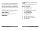
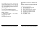
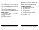
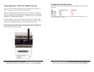
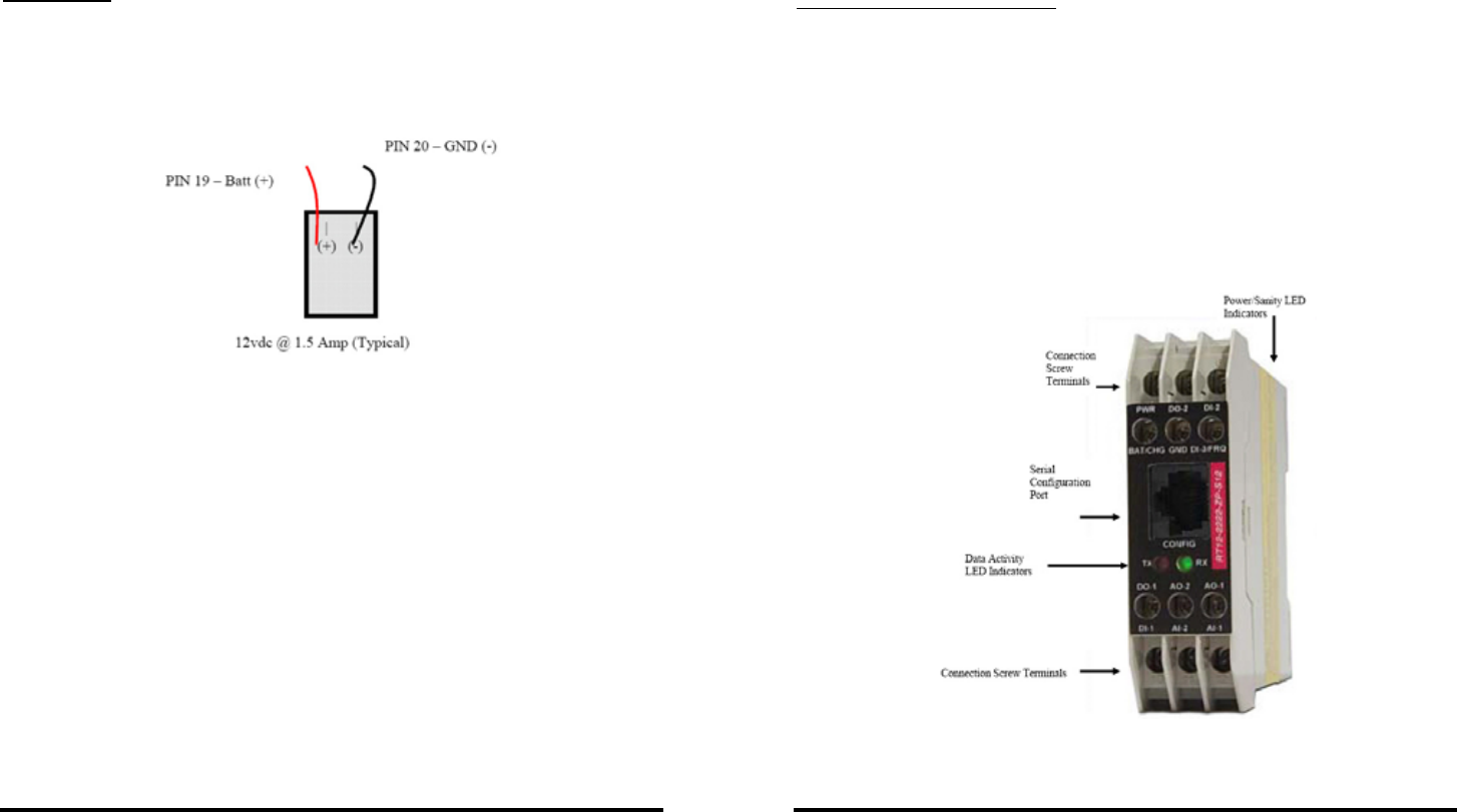
RT12-2222-ZP-S12 – Front Panel Identification
All analog voltage inputs and outputs are 12-bit, 0-5 Vdc. All digital inputs are from 0
to 12 Vdc. Digital inputs must fall to 0 Vdc as a LOW. Digital outputs are Open Drain.
Connection Screw Terminal Description
PIN NAME DESCRIPTION
1 BATT (+) Battery I/O. 10.5~28 Vdc
2 GND (-) Battery
3 DI 3 Frequency Input. <5 KHz
4 PWR (+) Power Input. 10~28 Vdc
5 DO 2 Digital Output-2
6 DI 2 Digital Output-2
7 DO 1 Digital Output-1
8 AO 2 Analog Output-2
9 AO 1 Analog Output-2
10 DI 1 Digital Input-1
11 AI 2 Analog Input-2
12 AI 1 Analog Input-1