


Manual Documentation Number: RT-12 series-4006m 9
B&B Electronics Mfg Co Inc – 707 Dayton Rd - PO Box 1040 - Ottawa IL 61350 - Ph 815-433-5100 - Fax 815-433-5104 – www.bb-elec.com
B&B Electronics – Westlink Commercial Park – Oranmore, Galway, Ireland – Ph +353 91-792444 – Fax +353 91-792445 – www.bb-europe.com
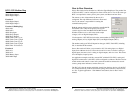
Note: This section assumes that your computer is equipped
with a serial port and you have installed the RT series
configuration software.
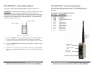
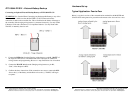
To Connect to a Controller:
1) Install the configuration software (setup.exe).
2) Apply Power to the controller. The heartbeat/sanity LED will begin to FLASH.
3) Connect the programming cable to your PC’s serial Port.
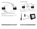
4) Launch the “Configuration” software.
5) You must select a communications port. Select “Comm”, “Serial” then the desired
serial port.
6) The “Connect” box will be Red.
7) Press the “Connect” Button. The “Asserting” check box will become checked.
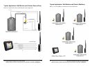
8) If the software successfully connects to the controller,
9) The “Connect” check box will become checked and the “Connect” button will turn
Green.
10) The software will begin retrieving configuration data from the controller you are
connected to. If all data boxes are not filled in refer back to step #6 in this section.
11) The software will indicate the type of device, Master or Slave.
12) For further programming features see, “Configuration/Programming Software
Setup.”
10 Manual Documentation Number: RT-12 series-4006m
B&B Electronics Mfg Co Inc – 707 Dayton Rd - PO Box 1040 - Ottawa IL 61350 - Ph 815-433-5100 - Fax 815-433-5104 – www.bb-elec.com
B&B Electronics – Westlink Commercial Park – Oranmore, Galway, Ireland – Ph +353 91-792444 – Fax +353 91-792445 – www.bb-europe.com
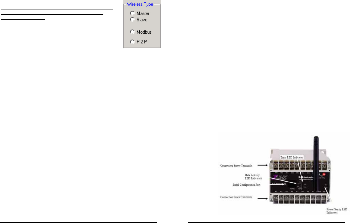
Chapter 2 – System Identification
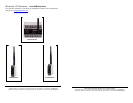
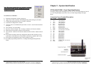
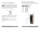
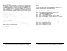
RT12-4444-9T-W20 – Front Panel Identification
All analog voltage inputs and outputs are 12-bit, 0-5 Vdc. All digital inputs are from 0
to 12 Vdc. Digital inputs must fall to 0 Vdc as a LOW. Digital outputs are Open
Drain.
Connection Screw Terminal Description
PIN NAME DESCRIPTION
1 AO 1 Analog Output-1
2 AO 2 Analog Output-2
3 AO 3 Analog Output-3
4 AO 4 Analog Output-4
5 DO 1 Digital Output-1
6 DO 1 Digital Output-2
7 DO 1 Digital Output-3
8 DO 1 Digital Output-4
9 GND (-) Power Input. Ground.
10 PWR (+) Power Input. 10-28 Vdc.
11 AI 1 Analog Input-1
12 AI 2 Analog Input-2
13 AI 3 Analog Input-3
14 AI 4 Analog Input-4
15 DI 1 Digital Input-1
16 DI 2 Digital Input-2
17 DI 3 Digital Input-3
18 DI 4 Digital Input-4
19 BAT (+) Battery I/O. 10.5-28 Vdc.
20 GND (-) Battery.