


Manual Documentation Number: RT-12 series-4006m 41
B&B Electronics Mfg Co Inc – 707 Dayton Rd - PO Box 1040 - Ottawa IL 61350 - Ph 815-433-5100 - Fax 815-433-5104 – www.bb-elec.com
B&B Electronics – Westlink Commercial Park – Oranmore, Galway, Ireland – Ph +353 91-792444 – Fax +353 91-792445 – www.bb-europe.com
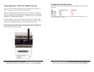
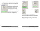
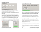
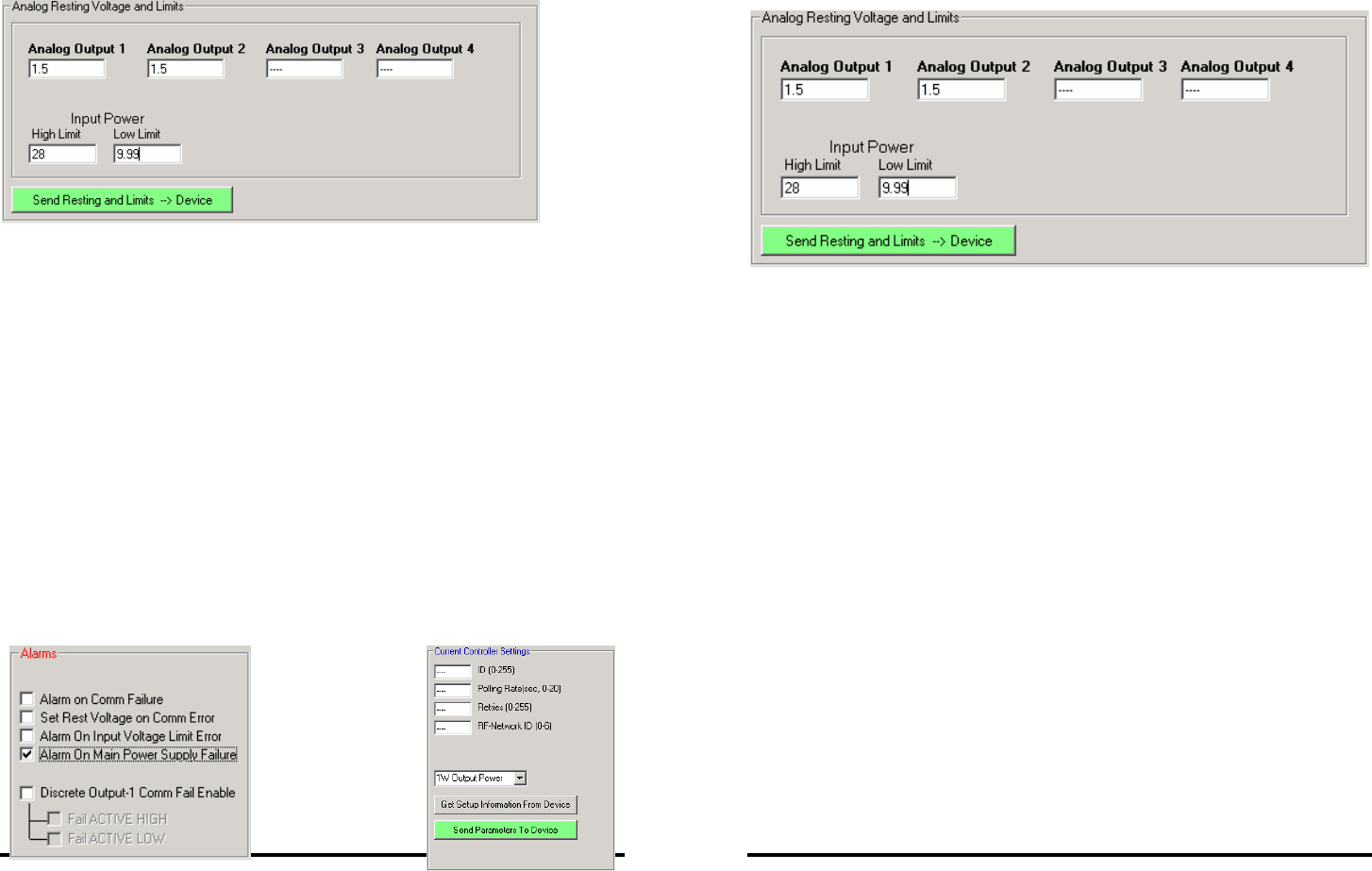
Input Voltage Alarm Limits
(Note: Four analog outputs available on specific RT-12 series models.)
The RT series RTU’s is capable of monitoring its input voltage. This section will
describe how to set and enable the “Input Voltage Alarm Limits”.
If the “Alarm On Input Voltage Limit Error” is enabled and the INPUT supply voltage
rises above the “High Limit” or falls below the “Low Limit” the respective RTU will
sound an alarm.
The alarm will stop sounding when the input supply voltage returns to ”normal” by
returning between the +/- limits determined by the “High/Low Limit Dead Band”. The
“Normal” +/- limits are calculated by subtracting the “High/Low Limit Dead Band”
from the “High limit” and adding the “High/Low Limit Dead Band” to the “Low Limit”
The configuration shown above will cause a HIGH alarm if the input supply voltage
rises above 28.0 VDC and will return to normal when the input supply voltage falls to
26.01 VDC.
The configuration above will cause a LOW alarm if the input supply voltage falls below
9.99 VDC and will return to normal when the input supply voltage rises to 11.98 VDC.
42 Manual Documentation Number: RT-12 series-4006m
B&B Electronics Mfg Co Inc – 707 Dayton Rd - PO Box 1040 - Ottawa IL 61350 - Ph 815-433-5100 - Fax 815-433-5104 – www.bb-elec.com
B&B Electronics – Westlink Commercial Park – Oranmore, Galway, Ireland – Ph +353 91-792444 – Fax +353 91-792445 – www.bb-europe.com
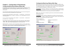
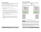
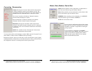
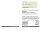
Analog Outputs Resting Voltage
(Note: Four analog outputs available on specific RT-12 series models.)
This section applies to Peer to Peer and Modbus systems. In peer to peer mode, the
master and slave communicate with each other and during the communication process
they share information. In the event of a communication failure, the updating process
will stop and if the Communications alarm is disabled the analog outputs for the
master and slave will be the last valid update.
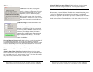
A communications error will occur if the number of consecutive failed polling
attempts exceeds the programmed number of retries. This count is reset if even one
valid communications update occurs before the number of retries expires and if the
RTU is a Modbus device, a communications of 2 minutes must laps.
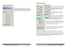
The analog output resting voltages provide a means to program the voltage outputs in
the event of a communications error.
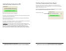
Due to the nature of wireless systems, communication failures may occur. The RT
series RTU’s allow you to program each of the analog outputs with a preset level in
the event of a communications failure. Each analog output can be programmed with
independent levels from 0 volts to 5 Vdc.
If the RTU is programmed to respond to a communications alarm and a
communications failure occurs, the respective RTU will force the outputs with your
preset levels. The outputs will return to normal once communications is reestablished.
To program the RTU to respond to communications failures select the “Set Rest
Voltage on Comm Error” and update the configuration by pressing the “Send Changes
To Device”.