


Manual Documentation Number: RT-12 series-4006m 31
B&B Electronics Mfg Co Inc – 707 Dayton Rd - PO Box 1040 - Ottawa IL 61350 - Ph 815-433-5100 - Fax 815-433-5104 – www.bb-elec.com
B&B Electronics – Westlink Commercial Park – Oranmore, Galway, Ireland – Ph +353 91-792444 – Fax +353 91-792445 – www.bb-europe.com
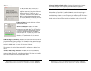
Controller Configuration
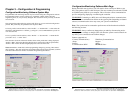
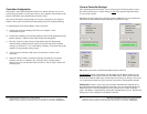
Selecting the “Get Setup Information From Device” button will allow you to view
existing setup parameters saved by the master or slave controller. The task bar on the
bottom of the Main screen should indicate “Profile = RTU”
This section will identify each parameter as well give a description of it respective
function. This section assumes that the Monitoring software is loaded and running.
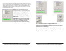
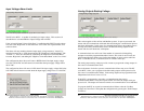
To capture/display data from the Master or Slave controller:
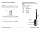
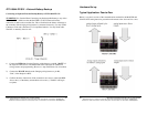
a) Connect the serial programming cable into your computer’s serial
communications port.
b) Connect the remaining end of the programming cable into the programming jack
labeled “Program”. Make sure the controller has powered applied.
c) Press the “Connect” button. Keep in mind that the data flow between the
controller being configured and its respective mate will stop. If the “Set Rest
Voltage on Comm Error” is set on the mating controller, it will alarm and set the
outputs to its programmed resting voltage.
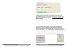
d) You may need to disconnect and connect several times to make a valid
connection.
e) When the software makes a connection with the controller the “Connected”
indicator will show as “Marked”, the “Controller Time” and date will be
displayed as well as all other data listed in each box. The “Connect” button will
also turn green.
32 Manual Documentation Number: RT-12 series-4006m
B&B Electronics Mfg Co Inc – 707 Dayton Rd - PO Box 1040 - Ottawa IL 61350 - Ph 815-433-5100 - Fax 815-433-5104 – www.bb-elec.com
B&B Electronics – Westlink Commercial Park – Oranmore, Galway, Ireland – Ph +353 91-792444 – Fax +353 91-792445 – www.bb-europe.com
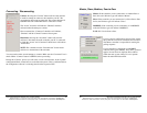
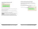
Current Controller Settings
This configuration block will allow you to set the respective RTU parameters such as
ID, subnet, polling rate, etc. These setting are vital
to the operation and performance
of your wireless system.
Parameters not set correctly may cause the system to malfunction or not communicate.
This block will affect different fields depending on the Wireless Type.
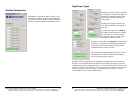
ID: Displays the current controller ID number between 0 and 255.
!WARNING! In Peer-to-Peer Mode, the ID numbers for the Master and Slave must
match and must not be repeated with any other Master/Slave Pairs with the same RF-
Network ID within the radio range of each respective wireless pair. Doing so will cause
cross talk between master/slave pairs and may cause harm to the equipment attached.
Polling Rate: In Peer-to -Peer mode, this parameter determines the sampling rate of
data passed between the Master and Slave controllers. It is also the update rate for the
Master and Slave’s analog and digital I/O. This parameter has no affect in Modbus
mode. The Master is responsible for starting the communications process. Therefore the
Polling rate is only configured on the Master controller.