


Manual Documentation Number: RT-12 series-4006m 1
B&B Electronics Mfg Co Inc – 707 Dayton Rd - PO Box 1040 - Ottawa IL 61350 - Ph 815-433-5100 - Fax 815-433-5104 – www.bb-elec.com
B&B Electronics – Westlink Commercial Park – Oranmore, Galway, Ireland – Ph +353 91-792444 – Fax +353 91-792445 – www.bb-europe.com
Chapter 1 – Introduction
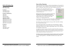
Theory of Operation
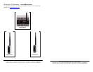
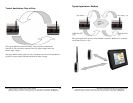
This manual will refer to two types of SCADA communications topologies, Peer to
Peer (P2P) and Modbus.
The Peer to Peer topology
consists of one “Master” and one “Slave” RTU. Analog
and digital I/O is communicated between the Master and Slave.
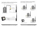
The Modbus topology
consists of one Modbus Master, and as many as 255
Modbus slaves. The Modbus master is responsible for requesting data from a
respective Modbus slave.
The ‘RT’ series RTU’s have several unique functions and features and has been
designed to replicate a wired sensor system. Transmission distances of up to 40 miles
(64 km), (depending on the radio type and with modified antennas), user
programmable sample/polling rates from 10 samples/sec to one sample every 20
seconds, programmable transmission retries, user programmable “full scale”
engineering units allow users to enter full scale for a respective sensor, just to name a
few.
The hardware architecture for RT series RTU’s are identical. Number of analog or
digital I/O depends on the type of RTU. Each respective RTU has Bi-directional
analog signal flow.
Other features include:
-Battery backup and in-circuit charging system,
-MODBUS-RTU-Slave Enhancements,
-Programmable main voltage failure alarm,
-Low and high input voltage alarm,
-Communications failure alarm,
-Programmable resting voltages on communication failure,
-Programmable Output to Active High or Low during Communications Failure,
-Report by exception if a respective input changes by a +/- percentage,
-Configurable Inputs to Digital, Frequency or Accumulator/Total.
An enhanced monitoring and configuration windows based program, allows you to
configure each controller as well as monitor data.
2 Manual Documentation Number: RT-12 series-4006m
B&B Electronics Mfg Co Inc – 707 Dayton Rd - PO Box 1040 - Ottawa IL 61350 - Ph 815-433-5100 - Fax 815-433-5104 – www.bb-elec.com
B&B Electronics – Westlink Commercial Park – Oranmore, Galway, Ireland – Ph +353 91-792444 – Fax +353 91-792445 – www.bb-europe.com
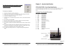
Your system may consist of two RT type wireless analog bridges or RTU. In Peer to
Peer mode, one controller must be programmed as the master and the other as the
slave. It is critical that your system be programmed properly. Confirm your system
configuration before using your system.
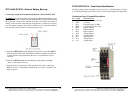
All configuration parameters may be retrieved by connecting to the respective
device’s serial configuration port. The wireless type and other parameters may be
adjusted or viewed.
For Peer-to-Peer mode, check and confirm the following:
___ Your system consists of one MASTER and one SLAVE. Do not allow two
masters or two slaves to communicate with each other. The devices may communicate
but a systems failure will occur.
___ Make sure the system ID’s and RF-Network ID’s match.
WARNING:
ID numbers for the Master and Slave must match and must not be repeated with
any other Master/Slave pairs with the same RF-Network ID within the radio
range of each respective wireless pair. Doing so will cause cross talk between
master/slave pairs.
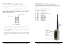
___ Make sure both Master and Slave have an antenna attached and installed correctly.
___ Make sure that the input power supply does NOT exceed 28 Vdc.
___ Make sure that the input power supply does NOT fall below 8.5 Vdc.
___ When power is applied to both the master and slave both units will communicate
with each other.
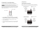
For Modbus Slave RTU mode, check and confirm the following:
___ Your system does not consist of two RT RTU/devices with the same Slave ID
numbers.
___ Each RTU/device has the same Radio ID and RF-Network ID numbers. Your
Modbus Master device will need to be connected to our Packaged Modbus Modem
(PMM) and will need to be configured with the same Radio ID and RF-Network ID
numbers as the Modbus Slave devices. The PMM may be configured to allow for an
RS-232 or RS-485 communications port.