


Manual Documentation Number: RT-12 series-4006m 15
B&B Electronics Mfg Co Inc – 707 Dayton Rd - PO Box 1040 - Ottawa IL 61350 - Ph 815-433-5100 - Fax 815-433-5104 – www.bb-elec.com
B&B Electronics – Westlink Commercial Park – Oranmore, Galway, Ireland – Ph +353 91-792444 – Fax +353 91-792445 – www.bb-europe.com
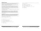
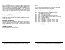
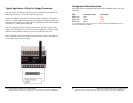
Power: 10.5~28 Vdc
Most DC power supplies rated from 10.5 to 28 Vdc @ 200mA, will work with the
RT12-2222-ZP-S12. Do not use a power supply rated less than 200 mA, doing so may
cause the RT12-2222-ZP-S12 to continuously reset. Make sure that the power supply
voltage is maintained between the programmable HIGH and LOW supply voltage
limits or an alarm may occur. If a rechargeable battery is used or if you are supplying
voltage to a sensor using the same power used to power the RT12-2222-ZP-S12, then
the input voltage will need to be adjusted to the proper voltage to maintain respective
equipment. Never exceed 28 Vdc damage, overheating to the controller will occur
causing the system to malfunction.
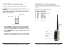
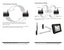
Data Activity LED Indicators
The RT12-2222-ZP-S12 RTU is equipment with three LED indicators. The
RED/GREEN pair labeled “RX” and ”TX”, indicate data transmit and data received.
The RED LED will blink when data is being transmitted The GREEN LED will blink
any time data is received.
Link/Sanity LED Indicators
The yellow LED indicator is locate internally and indicates proper system operation.
The second yellow LED indicator, labeled “Error”, will flash any thing an alarm is
program and the respective alarm is active. The Status LED indicator may be seen
through a small hole on the top of enclosure.
Serial RS-232 Interface
Used to configure the RTU. See “Software Setup”.
16 Manual Documentation Number: RT-12 series-4006m
B&B Electronics Mfg Co Inc – 707 Dayton Rd - PO Box 1040 - Ottawa IL 61350 - Ph 815-433-5100 - Fax 815-433-5104 – www.bb-elec.com
B&B Electronics – Westlink Commercial Park – Oranmore, Galway, Ireland – Ph +353 91-792444 – Fax +353 91-792445 – www.bb-europe.com
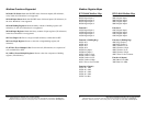
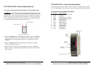
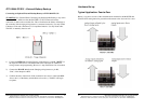
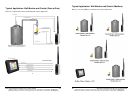
The RT12-2222-ZP-S12 has two rows of 6, screw type, connections. Using a common
type screwdriver, loosen the respective terminal screw, insert the respective wire and
tighten.
The front panel is stenciled with each Connection PIN number. Listed below are the
respective Connection numbers and Connection description.
Connection Screw Terminals Description
Pin 1: “Batt” (+) Battery Charge During Normal Main Power Input.
Battery Backup during Main Power Fails
Pin 2: “GND” (-) Power and Battery Ground
Pin 3: “DI 3” (+) Frequency Input. Do Not Exceed 5 KHz
Pin 4: “PWR” VIN(+) Main Supply 10.5 to 28.0, Must be > 13.0 to Charge
External Battery. Do Not Exceed 28 Vdc
Pin 5: “DO 2” (+) Digital Output - 2, Open Drain, Active Low, Output
Pin 6: “DI 2” (+) Digital Input - 2, Active Low, 0~12 Vdc
Pin 7: “DO 1” (+) Digital Output - 1, Open Drain, Active Low, Output
Pin 8: “AO 2” (+) Analog Output - 2, 0-5 Vdc
Pin 9: “AO 1” (+) Analog Output - 1, 0-5 Vdc
Pin 10: “DI 1” (+) Digital Input - 1, Active Low, 0~12 Vdc
Pin 11: “AI 2” (+) Analog Input - 2, 0-5 Vdc
Pin 12: “AI 1” (+) Analog Input - 1, 0-5 Vdc