


Installing the ET0010A
ETEP Installation Guide 31
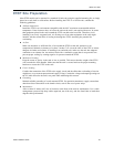
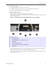
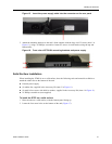
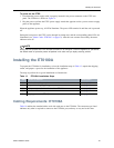
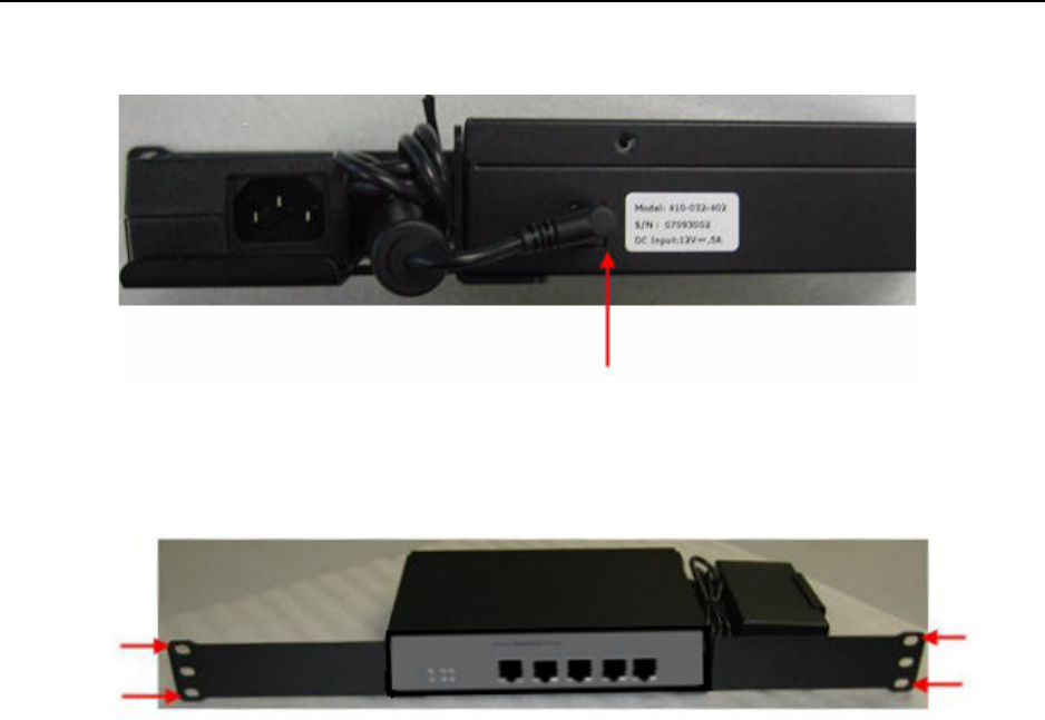
Figure 15 Insert the power supply cable into the connector on the rear panel
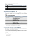
5 Attach the mounting brackets to the rack’s front supports with the large #10-32 screws (item 1 in
Figure 11), using a #2 Phillips screwdriver. Insert two screws in each bracket, using the top and
bottom holes.
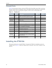
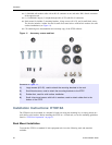
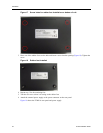
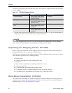
Figure 16 Front view of ET0010A mounting brackets and power supply
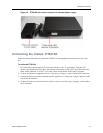
Solid Surface Installation
When installing the ET0010A on a solid surface, have the following tools and materials available to
attach the rubber feet to the bottom of the unit:
● External power supply
● (4) rubber feet, supplied in the Accessory Kit (item 3 in Figure 11).
● (4) small silver screws with built-in washers, supplied in the Accessory Kit (item 4 in Figure 11).
● #1 Phillips screwdriver (user-supplied)
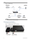
To install the ETEP on a solid surface:
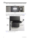
1 Place the unit on a solid surface, with the bottom panel facing up.
2 Locate the four screw holes on the bottom of the unit (Figure 17).