


Black Box®LB1350A/LB1351A
27
The broadcast protection indicates the relative amount of broadcast traffic that will be
forwarded by the Black Box® LB1351A, starting at 25% maximum and down to 3%
minimum. Default value is 25%.
The DSCP codes are represented as a series of 8 bytes, corresponding to 64 bits.
These bits correspond, in turn, to 64 different DSCP codes. If you wish, for instance, to
set code 45 as high priority, then bit 45 in this series needs to be set to ‘1’ (this is done
though the control menus, described later). Default values are all 0s (meaning all codes
are low priority).
The user priority codes are used in conjunction with the 802.1p based priority scheme.
For example, if a tagged frame arrives with a priority code of 6, the Black Box®
LB1351A will look priority code 6 to see if it is set as high or low priority and handle the
frame accordingly. Default values are low priority for codes 0-3 and high priority
for codes 4-7.
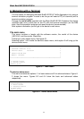
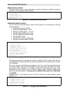
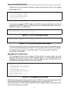
The device control menu
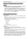
The device control menu, shown in figure 6-5, enables the user to change the different
settings and configuration of the Black Box® LB1351A
Device control
:
===============
1. TP port 1 control
2. TP port 2 control
3. TP port 3 control
4. FO port 4 control
5. Device reset
6. Basic device control
7. Advanced device control
8. Management control
0. return to main menu
Select (0-8):
figure 6-5 – device control menu
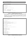
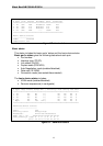
Options 1 through 4 will invoke the corresponding port’s control menu. Option 5 will
result in a device reset (which will return the relevant configuration settings to the
switches position). Options 6 and 7 will bring up the device control menu, respectively
and the eighth option will get you to the management virtual port’s settings.
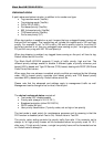
All control functions are located in the same tables of the device’s MIB sub-tree as their
corresponding status. The only exception is the management control functions, which
reside in the same table as the advanced device status.