


Conettix C900V2 | Installation Guide | 7.0 UL Standard 864 for Fire System Installations
.
Bosch Security Systems, Inc. | 8/08 | F01U087780-01 25
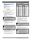
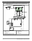
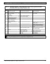
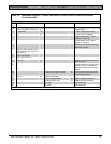
Table 11: Connection Sequence – C900V2 and Generic Control Panel in Separate Enclosures
(UL Standard 864)
Seq
C900V2 Connection Control Panel Connection Other Connection
1 RJ-45 PANEL connector to RJ-45 connector (telco dialer)
2 RJ-45 ETHERNET connector to LAN or WAN
3 – V terminal to –12 to –24 VDC (common)
4 V + to +12 to +24 VDC output
5 Power supply +BAT input to
battery 1 + terminal
6 Power supply –BAT input to
battery 2 – terminal
7 Battery 1 – terminal to battery 2 +
terminal (in series)
8 Install an EOL resistor for the
control panel across OUT2-L
and OUT1-R
9 OUT2-L to OUT1-L
10 OUT2-R to OUT1-R
11 OUT1-R to C900V2 enclosure closed-circuit
tamper switch
12 C900V2 enclosure closed-circuit
tamper switch to control panel
enclosure closed-circuit tamper
switch
13 24-hour zone input common to Control panel enclosure closed-
circuit tamper switch
14 OUT2-L to 24-hour zone input
15 Battery negative input to Battery negative terminal
16 Battery positive input to Battery positive terminal
17 AC input AC transformer
18 AC input AC transformer
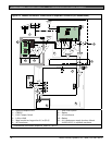
NOTE: The sequence numbers appear in the diagram in Figure 13.