


Conettix C900V2 | Installation Guide | Contents
4 Bosch Security Systems, Inc. | 8/08 | F01U087780-01
1.0 Introduction
The Conettix C900V2 Dialer Capture Ethernet Module
(referred to as the C900V2) links the digital dialer
(data output) from a control panel to an Ethernet
connection on a local area network (LAN) or wide area
network (WAN).
When the dialer sends a message, the C900V2
simulates a public switched telephone network (PSTN)
connection to the central station. The C900V2
decodes the digital dialer message and sends the
decoded signals by Ethernet connection to the
Conettix D6600 or D6100i. Communication
Gateway/Receiver (referred to as the receiver). When
the receiver acknowledges receipt of the message, the
C900V2 sends an acknowledge message to the
dialer. This process maintains true end-to-end
security.
The C900V2 has three modular connectors:
• TELCO connects to the PSTN.
• PANEL connects to a digital dialer.
• Ethernet connects to the network.
In Intercept Mode, the C900V2 connects the digital
dialer to a LAN or WAN. In Fallback Mode, the
C900V2 connects the dialer to the PSTN, which
bypasses the C900V2 from the phone circuit. The
C900V2 stays in Intercept Mode when its CPU is
working (Output 1 open). In Fallback Mode, the
C900V2 connects the dialer directly to the PSTN. The
C900V2 switches to Fallback Mode if there is a CPU
or network failure.
2.0 Installation
Failure to follow these instructions can
result in the system failing to transmit an
alarm. Bosch Security Systems, Inc. is
not responsible for improperly installed,
tested, or maintained devices.
Notify the central station and the local
authority before installing the C900V2 in
an existing system.
Disconnect all power to the control
panel before installing the C900V2.
2.1 Mounting
The C900V2 is static sensitive. Before
handling the circuit board, touch earth
ground to discharge any static electricity
from your body. Use a grounding strap
while installing the circuit board.
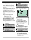
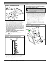
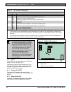
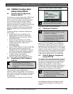
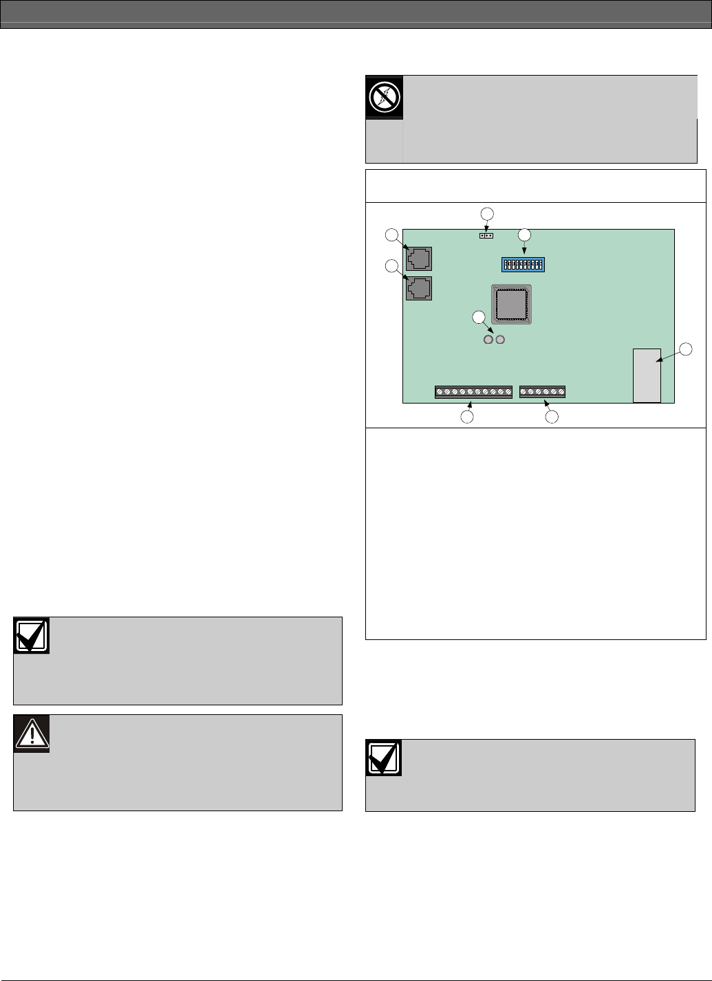
Figure 1: Location of Major Components
HL
2
1
4
8
5
3
67
1 – RJ-45 phone jack (to PSTN)
2 – RJ-45 phone jack (to control panel)
3 – High and low voltage selector (refer to
Section 3.1 on page 8)
4 – DIP switch (refer to Section 3.2 on page 8)
5 – RJ-45 Ethernet jack (to LAN or WAN)
6 – Power terminal strip (refer to Section 2.5 on
page 7)
7 – Input and output wiring terminals (refer to
Sections 2.3 and 2.4 on page 7)
8 – Dialer and system LEDs (refer to Section 3.3 on
page 10)
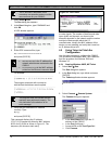
2.1.1 Optional Mounting Plate
Use an optional mounting plate (P/N: 40182) for
mounting the C900V2 on the door of a control panel
(D8103) or a fire control panel enclosure (D8109). You
cannot use the D8108A Attack Resistant Enclosure.
Mounting a C900V2 in a control panel
enclosure is approved by UL only when
used with a DS7400Xi as shown in
Figure 5 on page 6.
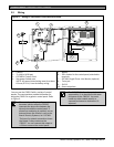
For the following procedure, refer to Figure 2 on page
5.
1. Insert the top hook of the supplied top (1) and
bottom plastic standoffs (2) into the mounting
plate brackets (3). Refer to Detail A.
2. Align the holes in the mounting brackets (3) and
the plastic standoffs (1 and 2).