


12
CONNECTING PROJECTOR
S–VIDEO
R–AUDIO–L
VIDEO/Y Cb/Pb Cr/Pr
VIDEO/Y Cb/Pb Cr/Pr
RESET
CONTROL PORT
AUDIO 2
RGB ANALOG IN/OUT
RGB DIGITAL
INPUT 1
INPUT 2
INPUT 3
R/C JACK
GBRH/V V
(
MONO
)
AUDIO 1
IN/OUT
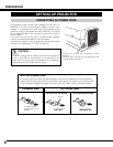
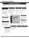
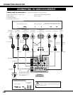
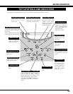
TERMINALS OF PROJECTOR
When controlling a computer
with the remote control unit
of this projector, connect the
mouse port of your personal
computer to this connector.
(See page 13.)
Connect S-VIDEO output
from video equipment to
this jack. (See page 14.)
Connect an audio output
from video equipment to
these jacks. (See page 14.)
CONTROL PORT CONNECTOR
COMPUTER AUDIO INPUT 1/
AUDIO MONITOR OUTPUT
JACK
AUDIO INPUT JACKSVIDEO INPUT JACKS S-VIDEO INPUT JACK
Connect composite video
output from video equipment
to VIDEO/Y jack or connect
component video outputs to
VIDEO/Y, Cb/Pb, and Cr/Pr
jacks. (See page 14.)
This terminal is switchable and
can be used as Computer Input
or Monitor Output. Set up the
terminal as either Computer
Input or Monitor Output properly
before using this terminal.
(See pages 13–14, 24.)
Note: This terminal outputs from the
5 BNC type computer input on
INPUT 2 jacks only.
COMPUTER INPUT/MONITOR
OUTPUT TERMINAL (ANALOG)
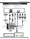
This projector has input and output terminals on its back for connecting computers and video equipment. Refer
to the figures on pages 12–14 and connect properly.
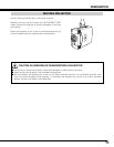
This projector uses a micro
processor to control the unit, and
only occasionally, this micro
processor may malfunction and
need to be reset. This can be done
by pressing the RESET button
with a pen, which will shut down
and restart the unit. Do not use
the RESET function excessively.
RESET BUTTON
When controlling a computer
with the remote control unit of
this projector, connect USB
terminal of your personal
computer to this terminal. (See
page 13.)
USB CONNECTOR (Series B)
Connect component video
output (Y, Cb, Cr or Y, Pb,
Pr) from video equipment to
VIDEO/Y, Cb/Pb, and Cr/Pr
jacks or connect computer
output {5 BNC Type (Green,
Blue, Red, Horiz. Sync, and
Vert. Sync.)} from computer
to G, B, R, H/V, and V jacks.
(See pages 13–14.)
5 BNC INPUT JACKS
When using the Wired/
Wireless remote control unit
as wired, connect the Wired
remote control unit to this
jack with an Audio cable
(Mini Plug [stereo]; not
supplied).
R/C JACK
Connect an audio
output (stereo) from a
computer to this jack.
(See page 13.)
COMPUTER AUDIO
INPUT 2 JACK
Connect a computer output
(Digital DVI-D type) to this
terminal.
The HD (HDCP Compatible)
signal can also be connected.
(See page 13.)
COMPUTER INPUT
TERMINAL (DIGITAL)
This terminal is switchable and
can be used as Computer
Audio Input 1 or Audio Monitor
Output (variable).
Set up the terminal as either
Computer Audio Input 1 or
Audio Monitor Output properly
before using this terminal.
(See pages 13, 24.)
Note: This terminal does not
output audio from INPUT 3.