


— 92 —
ESC p m n1 n2
[Function] Generating the specified pulses
[Code] <1B>H<70>H<m><n1><n2>
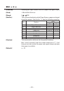
[Range] m = 0, 1, 48, 49
0
n1 255
0
n2 255
[Outline] The signals specified by “n1” and “n2” are output to the
connector pin specified by “m”.
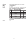
• “m” has the followings.
m Connector Pin
0, 48 Drawer Kick-Out pin No.2
1, 49 Drawer Kick-Out pin No.5
• The ON time is n1 × 2 ms, and OFF time n2 × 2 ms.
[Caution] • When “m” is beyond a definition range, no signal is output,
discarding “n1” and “n2”.
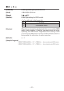
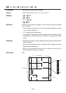
• The drawer drive duty must be within the following range:
ON time
ON time + OFF time
(The OFF time should be 4 times or more longer than the ON
time.)
[Default] The initial value for “m”, “n1” and “n2” is not defined.
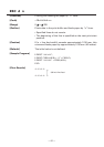
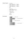
[Sample Program]
← Selects pin No. 2.
← Sets ON time to 10ms
← Sets OFF time to 100ms
0.2
LPRINT CHR$(&H1B) + “p”;
LPRINT CHR$(0);
LPRINT CHR$(5);
LPRINT CHR$(50);
END