


— 39 —
8. DRAWER KICK-OUT CONNECTOR AND POWER CONNECTOR
8.1 Specifications of Drawer Kick-Out Connector
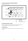
8.1.1 Drawer Kick-Out drive signal
A pulse specified by ESC p, DLE DC4 is output. In parallel interface mode, the
SW(+) state can be confirmed at No. 34 pin of the interface connector or by the
DLE EOT, GS a and GS r commands at the serial/parallel interface.
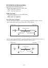
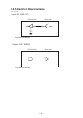
8.1.2 Electrical characteristics
• Drive voltage: DC 24 V
• Drive current: 0.8 A maximum (Within 510 ms)
• SW signal: Signal level “L” = 0 to 0.5 V
“H” = 3 to 5 V
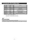
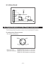
8.1.3 Connector Pin Configuration
Connector used: TM5RJ3-66 (Hirose) or equivalent
Applicable connector: TM3P-66P (Hirose) or equivalent
CAUTION:
• No output is produced while printing.
• The drawers 1 and 2 cannot be driven simultaneously.
• A solenoid used for the drawer should be of 36 Ω or more. The output current should
be kept at 0.8 A or less; otherwise, breakdown or burning could occur.
• This connector cannot be connected to a telephone line. Do not connect to anything
other than the solenoid.
61
SignalNo.
1
2
3
4
5
6
FG
DRAWER 1
DRSW
VDR
DRAWER 2
GND
Frame Ground
Drawer 1 drive signal
Drawer switch input
Drawer drive power supply
Drawer 2 drive signal
Common ground on circuits
Function