


10 PA-5EFL Ethernet 10BASE-FL Port Adapter Installation and Configuration
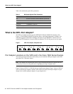
What Is the 5EFL Port Adapter?
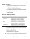
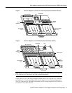
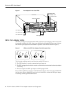
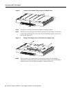
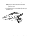
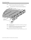
Figure 4 Port Adapters in the Cisco 7206
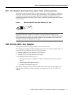
5EFL Port Adapter LEDs
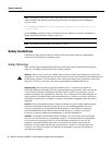
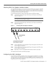
The 5EFL port adapter contains the enabled LED, standard on all port adapters, and one status LED
for each port, called the link LED. After system initialization, the enabled LED goes on to indicate
that the 5EFL port adapter has been enabled for operation. (The LEDs are shown in Figure 5.)
Figure 5 LEDs on the 5EFL Port Adapter, Partial Faceplate View
The following conditions must be met before the enabled LED goes on:
• The 5EFL interface is correctly connected and receiving power
• The 5EFL-equipped cardor chassis contains a valid microcode version that has beendownloaded
successfully
• The bus recognizes the 5EFL port adapter or 5EFL-equipped VIP2
If any of these conditions is not met, or if the initialization fails for other reasons, the enabled LED
does not go on. When a 10BASE-FL port is active, its link LED is on when the 5EFL port adapter
is receiving a carrier signal from the network.
H6422
2
ETHERNET 10BT
ENABLED
0
2
1
3
LINK
0
1
2
3
ENABLED
MII
LINK
RJ45
FAST ETHERNET
0
0
4
1
3
5
6
Port adapter slot 5
Port adapter slot 3
Port adapter slot 1
FAST SERIAL
EN
TD
TC
RD
RC
LB
CD
TD
TC
RD
RC
LB
CD
TD
TC
RD
RC
LB
CD
TD
TC
RD
RC
LB
CD
TOKEN RING
0
1
2
3
ETHERNET-10BFL
EN
RX
0
1
2
3
4
TX
RX
TX
RX
TX
RX
TX
RX
TX
Blank port adapter
Port adapter slot 6
Port adapter slot 4
Port adapter slot 2
MII
EN
RJ45
EN
RJ45
LINK
1O PWR
OK
RJ-45
CPU RESET
FAST ETHERNET INPUT/OUTPUT CONTROLLER
ENABLED
PCMCIA
EJECT
SLOT 0
SLOT 1
FE MII
Port adapter slot 0
PACKET OVER SONET/SDH
H6470
EN
RX
0
4
TX
RX
TX