


12 PA-5EFL Ethernet 10BASE-FL Port Adapter Installation and Configuration
VIP2 and the 5EFL Port Adapter
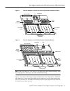
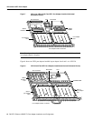
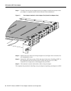
Figure 7 VIP2-15 or VIP2-40 with Two 5EFL Port Adapter Installed (Horizontal
Orientation Shown)
Note Port adapters have a handle attached, but this handle is not shown to allow a fullview of detail
on each port adapter’s faceplate.
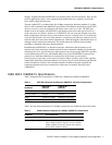
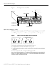
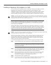
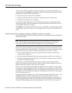
Figure 8 shows two 5EFL port adapters installed in port adapter slots 0 and 1 on a VIP2-50.
Figure 8 VIP2-50 with Two 5EFL Port Adapters Installed (Horizontal Orientation Shown)
H6472
Port adapter
slot 0
Port adapter
slot 1
Bus connector
ETHERNET-10BFLETHERNET-10BFL
EN
RX
0
1
2
3
4
TX
RX
TX
RX
TX
RX
TX
RX
TX
EN
RX
0
1
2
3
4
TX
RX
TX
RX
TX
RX
TX
RX
TX
DRAM
SIMMs
SRAM
DIMM U5
CPU Boot ROM
Port adapter handles not shown
U6
U2
U4
Bus connector
SRAM
daughter
card
Boot ROM
CPU
SDRAM DIMM
H11236
Port adapter handles not shown
ETHERNET-10BFLETHERNET-10BFL
EN
RX
0
1
2
3
4
TX
RX
TX
RX
TX
RX
TX
RX
TX
EN
RX
0
1
2
3
4
TX
RX
TX
RX
TX
RX
TX
RX
TX
5EFL in
port adapter
slot 0
5EFL in
port adapter
slot 1