


18 PA-5EFL Ethernet 10BASE-FL Port Adapter Installation and Configuration
VIP2 and the 5EFL Port Adapter
After you verify that the new 5EFL port adapter is installed correctly (the enabled LED goes on),
use the privileged-level configure command to configure the new interfaces. Be prepared with the
information you will need, such as the following:
• Protocols you plan to route on each new interface.
• Internet protocol (IP) addresses if you plan to configure the interfaces for IP routing.
• Whether the new interfaces will use bridging.
For a summary of the configuration options available and instructions for configuring the 5EFL
interfaces on the VIP2, refer to the appropriate configuration publications listed in the section “If
You Need More Information” on page 2.
The configure command requires privileged-level access to the EXEC command interpreter, which
usually requires a password. Contact your system administrator if necessary to obtain EXEC-level
access.
Selecting Chassis Slot, Port Adapter, and Ethernet 10BASE-FL Interface Port Numbers
The following section describes how to identify chassis slot, port adapter, and Ethernet 10BASE-FL
interface port numbers.
Note Although the processor slots in the seven-slot Cisco 7000 and Cisco 7507 and 13-slot
Cisco 7513 are vertically oriented and those in the five-slot Cisco 7010 and Cisco 7505 are
horizontally oriented, all models use the same method for slot and port numbering.
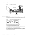
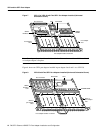
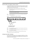
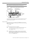
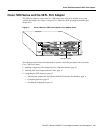
In the router, physical port addresses specify the actual physical location of each interface port on
the router interface processor end. (See Figure 14.) This address is composed of a three-part number
in the format chassis slot number/port adapter number/interface port number, as follows:
• The first number identifies the chassis slot in which the VIP2 is installed (as shown in the
example system in Figure 14).
• The second number identifies the physical port adapter number on the VIP2, and is either 0 or 1.
• The third number indicates the interface ports on each 5EFL port adapter are always numbered
in sequence as interface 0 through 4.
Interface ports on the VIP2 maintain the same address regardless of whether other interface
processors are installed or removed. However, when you move a VIP2 to a different slot, the first
number in the address changes to reflect the new slot number.
Figure 14 shows some of the slot port adapter and interface ports of a sample Cisco 7505 system.
For example, on a VIP2 equipped with a 5EFL port adapter in slot 3, the addresses of the first 5EFL
port adapter are 3/0/0 through 3/0/4 (chassis slot 3, port adapter slot 0, and interface ports 0–4), and
the addresses of the second 5EFL port adapter are 3/1/0 through 3/1/4 (chassis slot 3, port adapter
slot 0, and interface ports 0–4)
The first port adapter slot number is always 0. The second port adapter slot number is always 1. The
individual interface port numbers always begin with 0. For example, in Figure 14, the five
10BASE-FL interface ports on the 5EFL port adapter in the first port adapter slot in chassis slot 3,
have the following addresses: 3/0/0, 3/0/1, 3/0/2, 3/0/3, and 3/0/4. (See Figure 14.) The interfaces on
the second 5EFL port adapter have the following addresses: 3/1/0, 3/1/1, 3/1/2, 3/1/3, and 3/1/4.