


PA-5EFL Ethernet 10BASE-FL Port Adapter Installation and Configuration 11
5EFL Port Adapter Multimode Fiber-Optic Cable and Receptacles
5EFL Port Adapter Multimode Fiber-Optic Cable and Receptacles
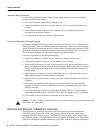
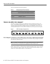
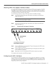
The interface connectors on the 5EFL port adapter are five pairs of (ST) receptacles, designated as
RX and TX. You can use all five connection pairs simultaneously or any combination of each pair
individually. Each connection pair supports IEEE 802.3 and Ethernet 10BASE-FL interfaces
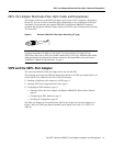
compliant with appropriate standards. Figure 6 shows the ST fiber-optic cable plug used for RX and
TX connections.
Figure 6 Ethernet 10BASE-FL Fiber-Optic Cable Plug (ST Type)
Note The 5EFL interfaces on a VIP2 are configured for 10 Mbps, half duplex, for a maximum
aggregate bandwidth of 50 Mbps for half-duplex. Cisco Systems does not supply ST-type
optical-fiber cables; these cables are available commercially. For ST-type, multimode optical-fiber
cable specifications and transmission distance limitations and requirements, refer to the section
“IEEE 802.3 10BASE-FL Specifications” on page 7.
VIP2 and the 5EFL Port Adapter
This section describes the 5EFL port adapter and its use with the VIP2.
The following sections provide additional information specific to the 5EFL port adapter and its use
on the VIP2 in Cisco 7000 series and Cisco 7500 series routers:
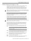
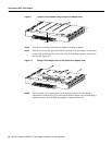
• Installing or Replacing a Port Adapter on a VIP2, page 13
• Attaching 5EFL Port Adapter Interface Cables, page 17
• Configuring the 5EFL Interfaces, page 17
— Selecting Chassis Slot, Port Adapter, and Ethernet 10BASE-FL Interface Port Numbers,
page 18
— Configuring the 5EFL Interfaces, page 17
— Checking the Configuration, page 20
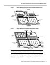
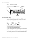
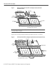
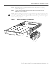
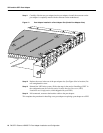
The 5EFL port adapter can be installed on the VIP2 in port adapter slot 0 and port adapter slot 1.
Figure 7 shows two 5EFL port adapters installed in port adapter slots 0 and 1 on a VIP2-15 or
VIP2-40.
H1348a