


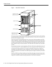

10 Cisco 12012 Gigabit Switch Router Card Cage Assembly Replacement Instructions
Removing and Replacing a Card Cage Assembly
Removing a DC-Input Power Supply
Perform the following steps to remove a DC-input power supply:
Caution Before performing any of the following procedure, ensure that power is removed from the
DC circuit. To ensure that all power is OFF, locate the circuit breaker on the panel board that services
the DC circuit, switch the circuit breaker to the OFF position, and tape the switch handle of the
circuit breaker in the OFF position.
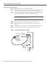
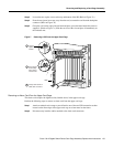
Step 1 Attach an antistatic wrist strap to yourself and to one of the two ESD connection sockets
located on the front edges of the upper card cage or to bare metal on the frame.
Step 2 If you have not already done so, turn OFF (O) the power switch on the DC-input power
supply.
Warning Voltages might be present on the DC-input power supply terminals. Turn off the power
source circuit breaker and remove the power supply before accessing the terminals.
Note Turning the power supply switch to OFF (O) releases a latch that secures the power
supply in the power supply bay.
Step 3 Locate and turn off the source DC circuit breaker that services the power supply you want
to remove. As an added precaution, tape the circuit breaker handle in the off position.
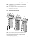
Step 4 Using a flat-blade screwdriver or a 10-mm nutdriver, turn the captive jackscrew
counterclockwise (eject) on the power supply faceplate to unseat the power supply from
the backplane power connector. Continue turning the jackscrew to disengage the
jackscrew from the power supply bay (approximately 12 revolutions).
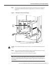
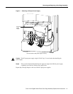
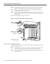
Step 5 Grasp the power supply handle and slide the power supply halfway out of the bay. (Refer
to Figure 4.)