


2 Cisco 12012 Gigabit Switch Router Card Cage Assembly Replacement Instructions
Product Overview
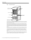
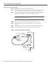
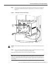
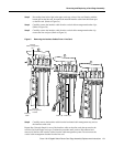
Figure 1 Cisco 12012—Front View
The lower card cage, located behind the air filter, has five keyed horizontal slots for cards containing
the switch fabric circuitry. The cards provide the physical pathway for data packet exchange between
the line cards in the upper card cage.
There are two types of cards installed in the lower card cage; the clock and scheduler card (CSC)
and the switch fabric card (SFC). Both types of cards are keyed to fit into specific slots in the lower
card cage. You can install the clock and scheduler card only in the top two slots and the switch fabric
card only in the lower three slots. The clock and scheduler card contains the system clock, switch
fabric scheduler circuitry, and the switch fabric. The switch fabric card contains only switch fabric
circuitry.
Below the lower card cage is a power supply bay. The Cisco 12012 can be configured for source AC
or source DC operation. A system configured for source AC operation must have a minimum of two
AC-input power supplies installed. You can install two additional AC-input power supplies for
redundancy and current sharing. Systems configured for source DC operation have one DC-input
power supply installed. You can install a second DC-input power supply for redundancy and current
sharing.
The Cisco 12012 has two blower modules; one located above the upper card cage and one located
below the power supply bay. They draw filtered cooling air in through both card cages and the power
supply bay to maintain acceptable operating temperatures for the internal components.
INPUT:
200-240V
~
10 A
50/60 HZ
2000 W
AC
OK
OUTPUT
FAIL
INPUT:
200-240V
~
10 A
50/60 HZ
2000 W
AC
OK
OUTPUT
FAIL
INPUT:
200-240V
~
10 A
50/60 HZ
2000 W
AC
OK
OUTPUT
FAIL
INPUT:
200-240V
~
10 A
50/60 HZ
2000 W
AC
OK
OUTPUT
FAIL
S
L
OT-0
ROUTE PROCESSOR
SLO
T
-
1
COL
L
LI
N
K
TX
RX
RJ-45
M
I
I
RE
SE
T
AUX
CONSOLE
E
JECT
ACTIVE
0
CARRIER
RX PKT
ACTIVE
1
CARRIER
RX PKT
ACTIVE
2
CARRIER
RX PKT
ACTIVE
3
CARRIER
RX PKT
Q OC-3/STM-POS
ACTI
V
E
0
CARRIER
RX CELL
OC-12/STM-4 ATM
OC-12/STM-4 POS
ACTIVE
0
C
A
RRIER
RX CELL
ACO/LT
ALARM
C
SC
0
F
AIL
1
0
1
2
E
NA
BL
E
D
CRI
T
ICAL
M
A
J
OR
MIN
OR
S
FC
ALARM 1 ALARM 2
H10476
Top blower module
(behind front cover)
Upper card cage
Lower card cag
e
(behind air filte
r)
Frame
Air filter tray
Power supply bay
B
ottom blower module
(
behind front cover)